C.E. Niehoff & Co. N1509/N1511/N2003 Troubleshooting Guides User Manual
Page 5
Page 5
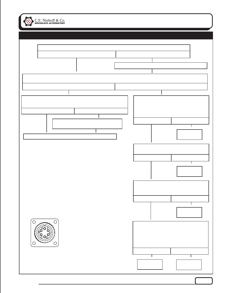
TG0014D
Section 3: Advanced Troubleshooting
(CONT’D)
Test for battery voltage at alternator 28 V B+ terminal. Does battery voltage exist?
Yes
No
Repair vehicle wiring as necessary. Continue test.
Run engine and re-test charging circuit for operation.
Chart 1 – 28 V LED Flashing AMBER – No 28V Alternator Output – Test Charging Circuit
Jumper 28 V B+ terminal on alternator to E terminal on regulator. Wait 10 seconds. Run engine. Does
alternator charge and is 28 V LED flashing GREEN?
Yes
No
Turn off engine, leave key on. Remove jumper wire. Go to E
terminal on regulator. Test for battery voltage going into E
terminal from battery. Does battery voltage exist?
Yes
No
STATIC TEST – MASTER SWITCH ON, KEY ON, ENGINE OFF
Repair vehicle circuit to E terminal. Ve-
hicle charging circuit test is complete.
T
T
T
T
T
T
Yes
Turn off engine, leave key on. Connect
jumper wire from pin A in harness plug to
B– terminal on alternator. Spark will occur.
Touch steel tool to shaft to detect significant
magnetism. is shaft magnetized?
No
T
T
T
Alternator is
defective.
T
Figure 3 – Alternator-to-Regulator Harness Plug
PIN CONNECTIONS
Pin A
F–
Pin B
SCR Gate
Pin C
B–
Pin D
28 V B+
Pin E
14V B+
Pin
F
AC
Yes
Test for battery voltage at pin D in harness
plug. Does battery voltage exist?
No
Alternator is
defective.
T
T
Yes
Connect DMM red lead to pin C on
harness plug. Connect black leak to alter-
nator B– terminal. Does continuity exist?
No
Alternator is
defective.
T
T
Yes
Set DMM to diode test. Connect DMM red
lead to pin F on harness plug. Connect
black leak to alternator B+ terminal.
Reverse leads. Meter should read OL in
one direction, and voltage drop in the other
direction. Do tests prove out?
No
Alternator is
defective.
T
Regulator is
defective.
T