C.E. Niehoff & Co. N1509/N1511/N2003 Troubleshooting Guides User Manual
Page 2
Page 2
TG0014D
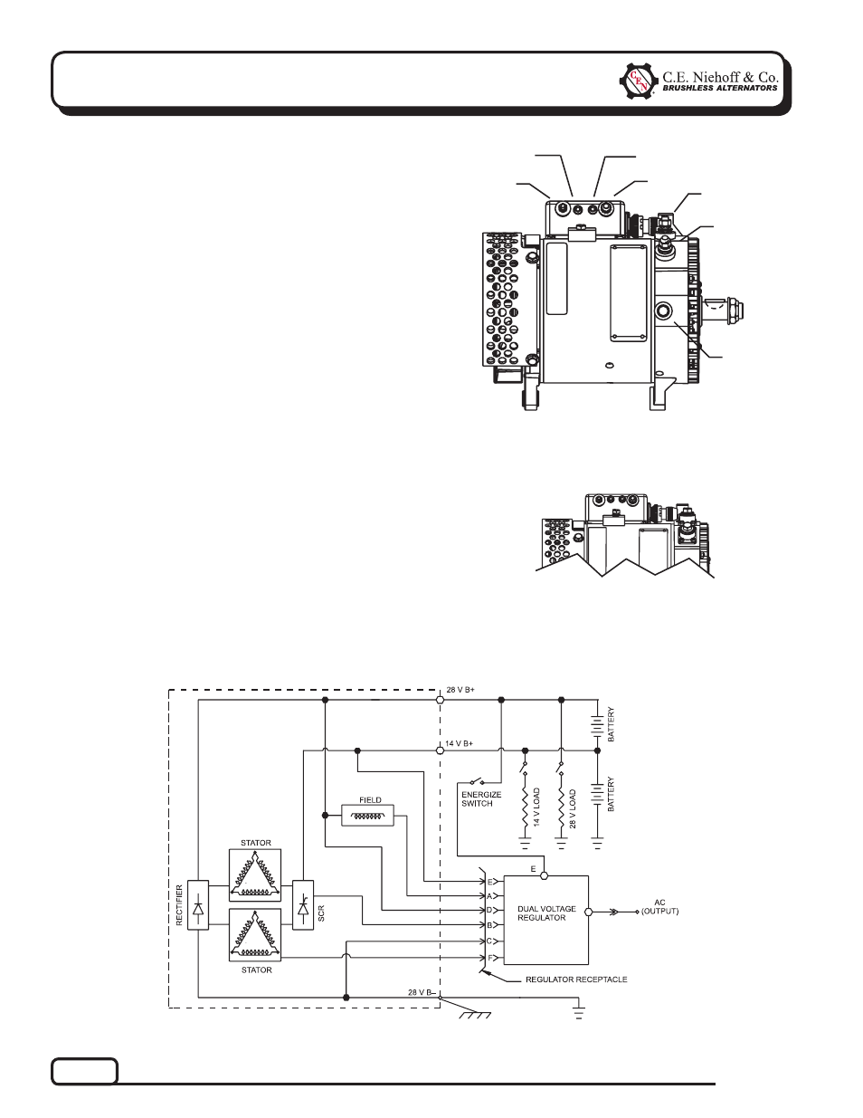
Section 1: Wiring Diagram
CEN N1509 and N1511 Dual Voltage
Alternator Description and Operation
N1509 and N1511 100 A (28 /14 V) dual voltage
alternators are internally rectified. All windings and
current-transmitting components are non-moving,
so there are no brushes or slip rings to wear out.
Energize switch (commonly an oil pressure switch)
activates regulator. Field coil is then energized. Upper
voltage (28 V) is rectified with standard diodes. Lower
voltage (14V) circuit output current is controlled by
SCRs in the drive end housing. Alternator output cur-
rent is self-limiting and will not exceed rated capacity
of alternator.
N3207 regulator used with some units:
• maintains alternator output voltage at regulated
settings as vehicle electrical loads are switched
on and off.
• maintains equal voltage across battery terminals
of series-connected batteries.
N2003 load and battery control device (LBCD) used
with these units provides dual-voltage reverse polarity
protection and independant control of battery-charg-
ing current.
B– Terminal
Figure 2 — N1509 and N1511 Alternators with Regulator
Figure 1 — N1509 Alternator and N3207 Regulator Termi-
nals
14 V B+
terminal
28 V B+
terminal
T
T
T
14 V System
LED Indicator
T
28 V System
LED Indicator
14V 28V
T
AC
E
E terminal
T
T
AC terminal
Figure 1 — N1511 Alternator and N3207 Regulator Termi-
nals