C.E. Niehoff & Co. C701/C701A Troubleshooting Guides User Manual
Page 8
Page 8
TG3E
Section C: Advanced Troubleshooting
(CONT’D)
Repair vehicle circuit to IGN terminal. Vehicle
charging circuit test is complete.
Set DMM to diode test. Connect black lead of DMM to B+ terminal on alternator. Connect
red lead to socket D on harness plug. DMM should read voltage drop. Reverse leads. DMM
should read OL.
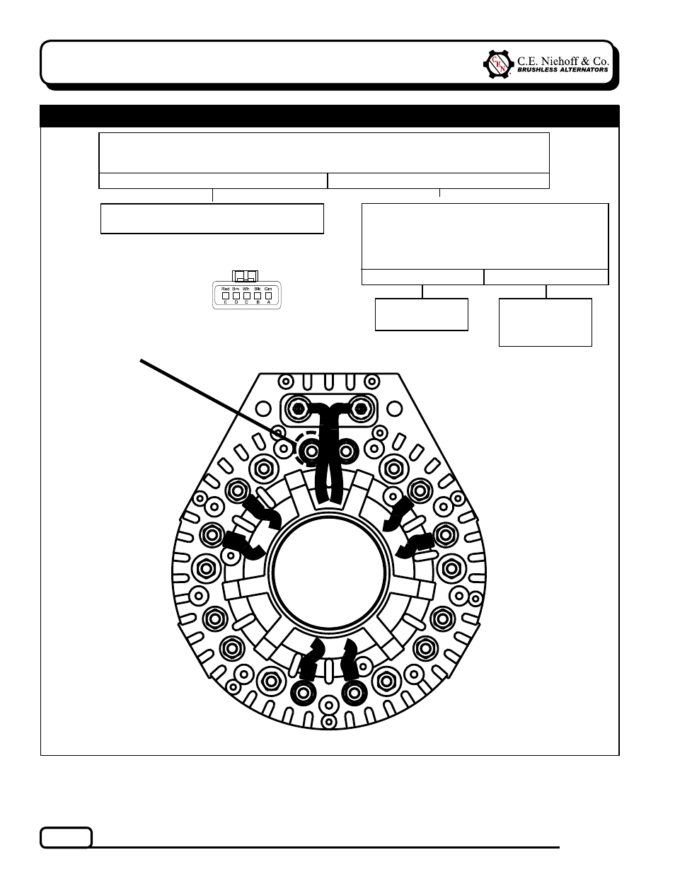
Check continuity of thermal switch inside control
unit: Remove drive end cover on alternator. With
DMM, check continuity between socket D on
harness plug and diode shown in Figure 7 below.
Does continuity exist?
Yes
No
Yes
No
Alternator is
defective.
Chart 4 – Continuation of Chart 2 or 3 as Noted
Thermal switch
in control unit
is defective.
Figure 7 – Diode Arrangement inside Drive End Housing
USE THIS DIODE
Figure 6 – Alternator-to-Regulator Harness Plug
SOCKET CONNECTIONS
Socket A B–
Socket B Field +
Socket C Field –
Socket D AC
Socket E B+
If you have questions about your alternator or any of these test procedures, or if you need to locate a Factory Authorized Service Dealer, please contact us at:
C. E. Niehoff & Co.• 2021 Lee Street • Evanston, IL 60202 USA
TEL: 800.643.4633 USA and Canada • TEL: 847.866.6030 outside USA and Canada • FAX: 847.492.1242
E-mail us at [email protected]