Page 6 tg3e – C.E. Niehoff & Co. C701/C701A Troubleshooting Guides User Manual
Page 6
Page 6
TG3E
Section C: Advanced Troubleshooting
(CONT’D)
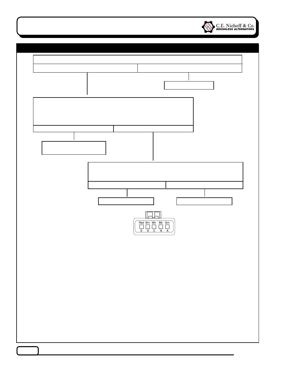
Chart 2 – No Air-Conditioning/Alternator Warning Light On
Yes
No
Connect DMM red lead to D+ (or P) terminal on regulator. Connect black lead
to alternator B– terminal.
At D+ terminal – is regulator setpoint voltage present?
At P terminal – is 12 V to 18 V present?
Stop engine. Alternator is good.
Check vehicle wiring.
Yes
No
Stop engine. Unplug alternator-to-regulator harness. Set DMM to Diode Test.
Connect DMM red lead to socket D on alternator-to-regulator harness plug.
Connect black lead to alternator B+ terminal. Does continuity exist?
Regulator is defective.
Go to Chart 4, page 8.
Yes
No
With engine running, verify operation of charging system. Is regulator setpoint voltage present?
Go to Chart 3, page 7.
Figure 4 – Alternator-to-Regulator Harness Plug
SOCKET CONNECTIONS
Socket A B–
Socket B Field +
Socket C Field –
Socket D AC
Socket E B+
- 5-Pin Connector Extended Wiring Harness Installation (1 page)
- 6-Pin Connector Extended Wiring Harness Installation (1 page)
- 6-Pin Connector Extended Wiring Harness W_O Fuses Installation (1 page)
- 100: Regulator Upgrade (1 page)
- 200 & 300: Regulator Upgrade Installation (2 pages)
- 600/700/800 Service Tool (1 page)
- A1-102/A1-104 Installation (2 pages)
- A2-149/A2-155 Regulator Installation (1 page)
- A2-213/A2-214 Regulator Installation (1 page)
- A2-317 Regulator Installation (1 page)
- A2-325/A2-330/A2-336 Regulator Installation (1 page)
- A2-334/A2-335 Regulator Installation (1 page)
- A2-337 Regulator Installation (1 page)
- A2-341/A2-346 Regulator Installation (1 page)
- A2-344/A2-348/A2-350 Regulator Installation (1 page)
- A2-349 Regulator Installation (1 page)
- A3-201 Adjustable Pulley Installation (2 pages)
- A6-141 & A6-143 Fan Guard Screw Replacement (1 page)
- A7-113/114/115 Stator & Shell Assy Replacement (1 page)
- A8-128 Power Management System Installation (1 page)
- A8-219 Low Frequency EMC Filter Assembly Installation (1 page)
- A9-305 Med-to-High Frequency EMC Filter Assembly Installation (2 pages)
- A9-307 Alternator Voltage Filter Instructions (1 page)
- A9-309 Inline Harness Instructions (1 page)
- A9-462 Energize Interrupt Switch Installation (1 page)
- A9-4011 Temperature Sense Lead Instructions (1 page)
- A9-4036 TV/J1939 Harness Installation (1 page)
- A9-4039/A9-4050 Temperature-Voltage Sense Harness Instructions (1 page)
- A9-4056 Temperature Sensor Replacement (1 page)
- C102/C102-1 Installation (2 pages)
- C130/C131/C132 Inst/Parts Rep/TG Combo Guide (12 pages)
- C130 & C132 Alternator Installation (4 pages)
- C131 Alternator Installation (4 pages)
- C180etc and C181etc Installation (4 pages)
- C190 Series Installation (4 pages)
- C321 Alternator Installation (1 page)
- C326 Installation (1 page)
- C510 Alternator Installation (2 pages)
- C520 Alternator/A2-326 Regulator w/Extended Wiring Harnesses Installation (1 page)
- C524, C524-1, -3, -4 Alternator/A2-334 & A2-335 Regulator Installation (1 page)
- C527 Alternator Installation (1 page)
- C540 Alternator Installation (2 pages)
- C600 & C700: Stator Change Instructions (1 page)
- C600: A4-106 Tension Link Adjuster Instructions (2 pages)
- C612: A9-169 Upgrade Bearing Kit Instructions (1 page)