Quick diagnostic, Caution – C.E. Niehoff & Co. C653/C653A/C625 Troubleshooting Guides User Manual
Page 7
Page 7
TG13G
Chart 2 –
No Alternator Output –
Quick Diagnostic
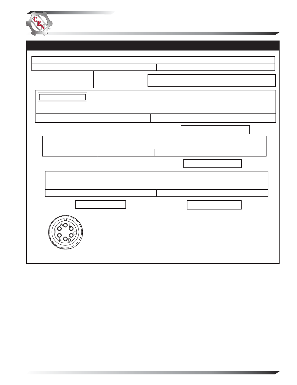
Figure 7 – Alternator-to-Regulator Harness Plug
PIN CONNECTIONS
Pin A
F–
Pin B
Phase
Pin C
B–
Pin D
B+
Pin E
D+
Pin
F
F+
With engine running, does battery voltage exist at alternator B+ terminal and regulator IGN terminal?
Yes
No
Repair vehicle harness circuit to IGN terminal on regulator
or B+ terminal on alternator.
Yes
No
Alternator is defective.
With DMM on resistance scale, ensure that the field resistance measured between pins F and A in
harness plug is about 1.2 (±0.2) ohms.
Yes
No
Alternator is defective.
Install a jumper from pin F in harness plug to B+ terminal on alternator. Momentarily (1 sec.) jumper
pin A in harness plug to alternator B– terminal. Touch shaft with steel tool to detect significant magne-
tism. Is shaft magnetized?
Yes
No
Go to Chart 3, page 8.
Regulator is defective.
Unplug alternator-to-regulator harness. Connect DMM across pin D and pin C in harness plug. Does battery
voltage exist?
When conducting this step, ensure that the probes do not touch other pins, as an arc may damage the
wiring in the harness.
CAUTION
Section D: A2-214 Advanced Troubleshooting
(CONT’D)