C.E. Niehoff & Co. C653/C653A/C625 Troubleshooting Guides User Manual
Page 2
Page 2
TG13G
Section A: Wiring Diagrams
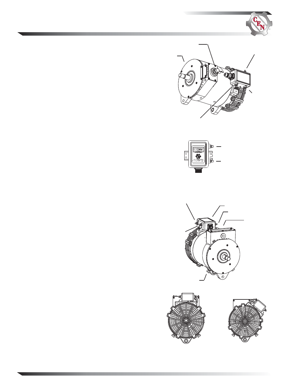
B– terminal
stud
P
terminal
IGN terminal
Figure 1 — C625 Alternator Terminals
B+ terminal stud
D+ terminal
Figure 3 — C653/C653A Alternator Terminals
B– terminal
stud
D+ terminal
IGN terminal
(A2-214 only)
B+ terminal
stud
(on rear of
control unit)
P
terminal
C653A
ADE View
C653
ADE View
D+ terminal
R terminal
Figure 2 — A2-146 and A2-153 Regulator Terminals
(Also Used with C653, C653A)
CEN C653/C653A and C625 Alternators
Description and Operation
C653/C653A and C625 28 V (260 A) alternators are
self-rectifying. All windings and current-transmitting
components are non-moving, so there are no brushes
or slip rings to wear out.
When controlled by the
A2-146 or A2-153 regulator,
these alternators become self-energizing through inter-
nal diode trios. Residual magnetic field induces small
voltage in stator and energizes field coil. Field coil con-
tinues receiving incremental voltage until full voltage is
achieved. AC is rectified into DC output through diodes.
Regulator controls voltage output. Regulator has:
• D+ terminal to provide a signal to vehicle electrical
system, confirming alternator operation
• P terminal to provide an optional AC voltage tap.
When controlled by the
A2-214 regulator, these alter-
nators become externally energized through the IGN
terminal, connected to a switched power source to turn
on regulator. See wiring diagram, Figure 5 on page 3.
Regulator has:
• D+ terminal that can provide signal to vehicle
electrical system, confirming alternator operation.
• P terminal that can provide an optional AC voltage
tap.
• Overvoltage cutout (OVCO). See page 6.
• Green lens LED. See page 6.
When
C653 alternator is controlled by the A2-338
regulator, the alternator becomes self-energized through
sensing of alternator rotation through AC circuit.
Residual magnetic field induces small voltage in stator
and energizes field coil. Field coil continues receiving
incremental voltage until full voltage is achieved.
Regulator controls voltage output. See wiring diagram,
Figure 4 on page 3. A2-338 regulator has:
• P terminal that can provide optional AC voltage tap.
• D+ terminal that can provide DC voltage signal to
vehicle electrical system, confirming alternator
operation.
• Overvoltage cutout (OVCO) function. See page 10.
• Tricolored LED. See page 10.
• T terminal to connect optional A9-4011 temperature
sense lead to adjust regulator setpoint to maintain
charge voltage (or negative temperature compensa-
tion) by sensing ambient temperature within the
battery box. If temperature sense lead is not connect-
ed, the regulator will operate at 27.5 V.
T terminal
(A2-338 only)