C.E. Niehoff & Co. C633 Troubleshooting Guides User Manual
Page 2
Page 2
TG80A
Section A: Description/Operation
CEN C633 Alternator/Regulator Description and Operation
C633 28 V 220 A alternator with optional 28 V/14 V (50 A maximum on 14 V) is internally rectified. All windings and
current-transmitting components are non-moving, so there are no brushes or slip rings to wear out.
This alternator is externally energized when the battery master switch on the vehicle is turned on and provides power
to the regulator through the IGN circuit. Regulator monitors alternator rotation and provides field current only when it
detects alternator shaft rotating at suitable speed.
After regulator detects alternator rotation, it gradually applies field current (soft start), preventing an abrupt mechanical
load on accessory drive system. The soft start may take up to 10 seconds at full electrical load. AC is rectified into DC
output through diodes in drive end rectifier housing and supplied to the battery from the alternator B+ terminal. See
schematic diagram on page 3. Alternator output current is self-limiting and will not exceed rated capacity of alternator.
The regulator maintains alternator output voltage at regulated settings (see below) as vehicle electrical loads are
switched on and off.
Battery type selection and battery maintenance/function are the sole responsibilities of the customer.
A2-355 regulators furnished with some units include:
• External IGN terminal for energize connection.
• AC terminal for optional AC voltage tap. AC terminal signal frequency (Hz) x 10 = alternator shaft rpm.
• Optional single or dual voltage operation.
—Allows single-voltage (28 V only). 14 V is not available as a single-voltage application with this regulator.
—Allows optional 28 V/14 V dual voltage operation only from this regulator when phase cable from alternator is
connected to regulator and 14 V cabling from vehicle is attached to regulator 14 V terminal.
• Overvoltage cutout (OVCO) function. This regulator has OVCO (overvoltage cutout) that will trip at vehicle electrical
system voltage above 32 volts in a 28 V system or 16 V in a 14 V system that exists longer than 2 seconds. OVCO
feature detects high voltage and reacts by signaling relay in alternator field circuit to open. This turns off alternator.
OVCO circuit is reset when engine is restarted.
• Regulator has negative temperature compensation. Setpoints are 28.0± 0.2 V and 14.0 ± 0.2 V at 75°F.
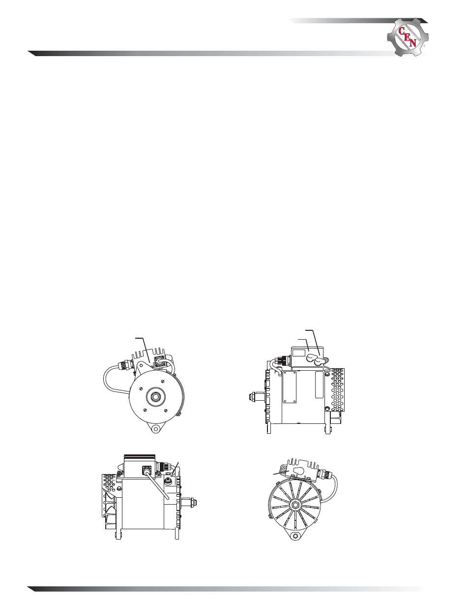
B– terminal
Figure 1 — C633 Alternator and A2-355 Regulator Terminals
14 V B+
terminal
28 V B+
terminal
14 V
AC
IGN
AC terminal
IGN terminal