Cen c622 alternator description and operation, Danger – C.E. Niehoff & Co. C622 Troubleshooting Guides User Manual
Page 2
Page 2
TG0011A
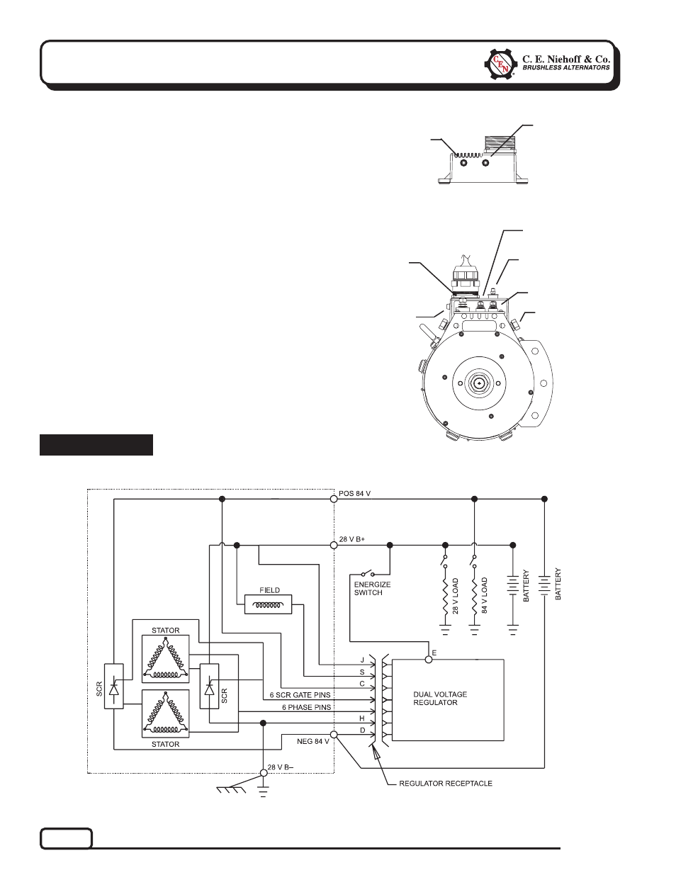
Section 1: Wiring Diagram
CEN C622 Alternator
Description and Operation
C622 28 V 100 A/84 V 50 A alternator is internally
rectified. All windings and current-transmitting
components are non-moving, so there are no brushes
or slip rings to wear out. This unit is externally
energized through an energize switch (commonly an
oil pressure switch), which activates regulator. Field
coil is then energized. 84 V system is not energized
until 28 V system is energized. 84 V and 28 V circuit
output currents are controlled by separate SCRs in
the drive end housing. Alternator output current is
self-limiting and will not exceed rated capacity of
alternator.
A2-307 regulator used with these units:
• maintains alternator output voltage at regulated
settings as vehicle electrical loads are switched
on and off.
• monitors 28 V and 84 V systems separately.
A2-604 battery charge equalizer and A9-069 harness
used with these units:
• equalizes six 12 V batteries connected in series.
• turns on when charge voltage is above 78 volts.
28 V B– Terminal
(either side)
28 V B+
Terminal
28 V E Terminal
Figure 2 — C622 Alternator with Regulator
Figure 1 — C622 Alternator Terminals
POS 84 V terminal
NEG 84 V terminal
T
T
T
T
T
T
T
T
T
T
T
T
T
T
T
T
TT
T
T
T
T
T
T
T
Tricolor
diagnostic LEDs
(2 side-by-side)
T T T T T
HIGH VOLTAGE. Use extreme
caution when working around 84 V
system. Severe personal injury or death will result from contact.
DANGER
A2-307 Regulator LEDs
84 V LED
Indicator
T
T
T
T
T
28 V LED
Indicator
T T T T T
84 V 28 V