Caution – C.E. Niehoff & Co. C613/C615/C620/C623/C634 Troubleshooting Guides User Manual
Page 4
Page 4
TG75B
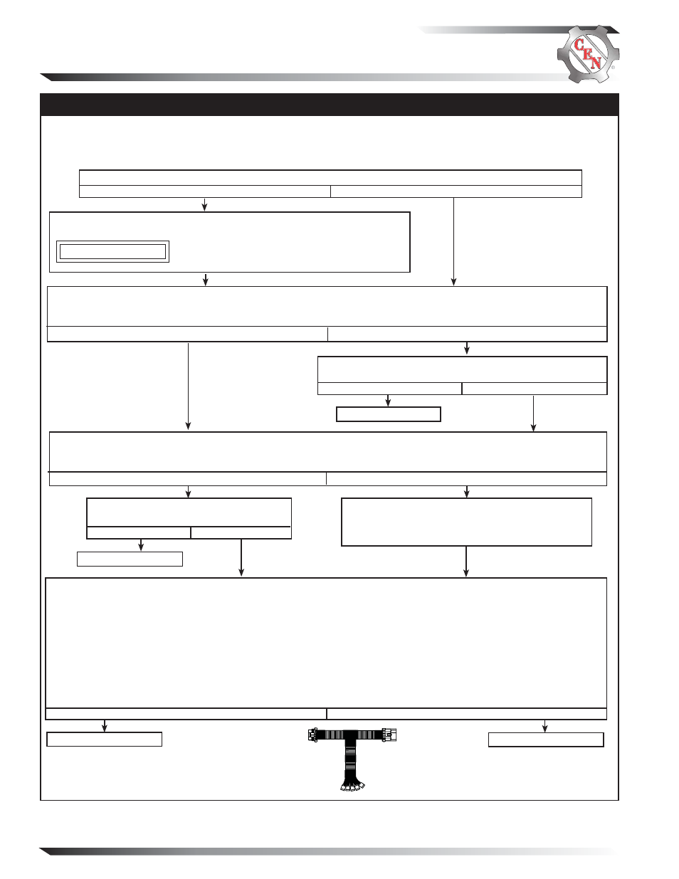
Section C: On-Vehicle Troubleshooting
Yes
No
Is there a battery isolator in the system?
No Alternator Output – Test Charging Circuit
MASTER BATTERY SWITCH ON, KEY ON, ENGINE ON: Test for battery voltage at B+ terminal on alternator
to ground, then at F+ terminal on regulator to ground, and finally at IGN terminal on regulator to ground.
Does battery voltage exist at all three locations?
Yes
No
MASTER BATTERY SWITCH ON, KEY ON, ENGINE OFF: Install one jumper wire from B+ terminal on alterna-
tor to F+ terminal on regulator. Add second jumper wire from B+ terminal on alternator to IGN terminal on
regulator. Touch shaft with steel tool to detect significant magnetism. Is shaft magnetized?
Yes
No
Figure 5 – A10-115 Inline
Harness Tool Socket
Connections
SOCKET CONNECTIONS
Socket A B–
Socket B Field +
Socket C Field –
Socket D Phase (R)
Socket E B+
Test field circuit. Readings of all three tests must pass:
1. Battery voltage test: Connect DMM red lead to socket E in test tool. Connect DMM black lead to socket A in test
tool. Battery voltage should exist.
2. Field coil resistance test: Set DMM on Ohms test. Field resistance measured between sockets B and C in test tool
should measure nominal 1.2 ± 0.2 ohms. Field coil is defective if reading is less than 0.5 ohms or greater than 3 ohms.
3. Significant magnetism test:
a. Securely connect one jumper wire between sockets B and E in test tool.
b. Securely connect one end of a second jumper wire to socket C on the test tool.
c. Momentarily (1 sec.) touch other end of
second jumper wire to ground on alternator case. Spark will occur at
ground on alternator case. Touch steel tool to shaft to detect significant magnetism.
Run engine and re-test charging circuit.
Is charging system performing properly?
System is operative.
Yes
No
Yes
No
Alternator is defective.
Remove both jumper wires. Disconnect alternator-
to-regulator harness plug at regulator and connect
CEN A10-115 inline test tool to harness plug end
only. Make sure connections are secure.
If you have questions about your alternator or any of these test procedures, or if you need to locate a Factory Authorized Service Dealer, please contact us at:
C.E. Niehoff & Co.• 2021 Lee Street • Evanston, IL 60202 USA
TEL: 800.643.4633 USA and Canada • TEL: 847.866.6030 outside USA and Canada • FAX: 847.492.1242
E-mail us at [email protected]
Before starting diagnostic sequence, verify the following and repair/replace if not to spec:
• batteries for state-of-charge (12.3-12.6 V), condition, and secure connections
• master battery switch for function
Install temporary jumper between one battery terminal and alternator
terminal on isolator. Use minimum 12 AWG wire.
CAUTION
Do not operate charging system more than two minutes
with jumper installed. Charging system voltage will be
abnormally high and damage other components.
Regulator is defective.
Repair vehicle wiring as necessary. Run engine and re-test
charging circuit. Is charging system performing properly?
System is operative.
Yes
No
A B C D E