C.E. Niehoff & Co. C613/C615/C620/C623/C634 Troubleshooting Guides User Manual
Page 2
Page 2
TG75B
Section A: Alternator and Regulator
CEN C613, C615, C620, C623, and C634 Alternators with A2-128 Regulator
C613 (14 V, 290 A), C615 (14 V, 340 A), C620 (14 V, 340 A), C623 (14 V, 290 A), and C634 (14 V, 350 A) alternators
are internally rectified. All windings and current-transmitting components are non-moving, so there are no brushes
or slip rings to wear out.
These alternators are externally energized when the battery master switch on the vehicle is turned on and provides:
• power to the regulator at its IGN terminal.
• field coil power supply from the battery through the F+ terminal on the regulator. If a battery isolator is used in
the system, the F+ terminal must be connected directly to the B+ terminal on the battery. If a battery isolator is
not used in the system, the F+ terminal must be jumpered to the alternator B+ terminal so that the field circuit
becomes activated.
AC is then rectified into DC output through diodes in drive end housing and supplied to the battery from the alternator
B+ terminal. See Figure 4 on page 3. Regulator maintains alternator output voltage at pre-determined regulated setting
(see below for setpoints) as vehicle electrical loads are switched on and off.
A2-128 regulator used with all units is designed to limit output current so output current will not exceed rated capacity
of alternator. Regulator has a P terminal for optional AC voltage tap. P terminal signal frequency (Hz) x 10 = alternator
shaft rpm.
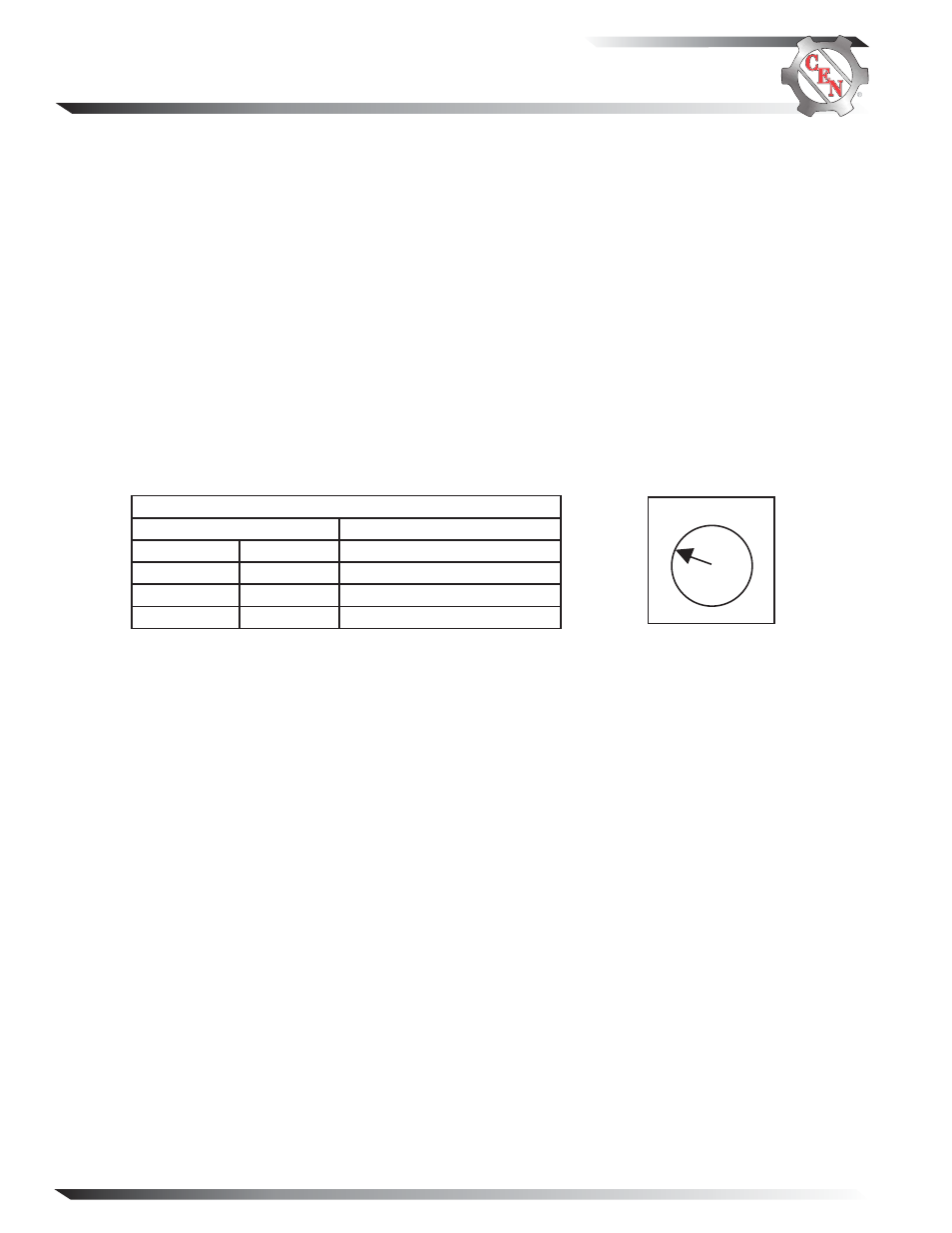
Regulator fixed (flat temperature compensation) setpoints shown in Table 1 are selected based on battery type. Battery
type selection and battery maintenance/function are the sole responsibilities of the customer.
Figure 2—Voltage Setpoints
1
2 3
4
Electromagnetic interference (EMI) is suppressed with internal filters to acceptable levels defined by the Society of
Automotive Engineers (SAE) specification J1113/41. C613, C615, C620, C623, and C634 alternators and A2-128 regulator
have demonstrated electromagnetic compliance (or compatibility) by being tested in accordance to the limits defined by
SAE J1113/41 standards for EMI suppression. However, these alternators and regulator will not reduce EMI from
sources such as;
• vehicle digital systems
• wireless links
• digital devices
• antennas
• poor cable routing practice
• improper vehicle wiring
• battery imbalance
...and other sources that cause EMI.
If EMI continues after addressing the above conditions, consult an electromagnetic compliance (or compatibility) special-
ist to determine EMI source and potential resolutions.
Table 1— Voltage Setpoint Switch Position
Voltage Setpoints (±0.2 V)
Battery Type
Position 1
14.0 V
Maintenance (D Category)
Position 2
14.4 V
Maintenance-free (Group 31)*
Position 3
14.8 V
Maintenance-free (Group 31)*
Position 4
15.5 V
Battery Isolator Setpoint
* Group 31 batteries: If boiling or excessive gassing occurs with high voltage
setpoint (position 3), change to medium voltage setpoint (position 2).