Quick diagnostic – C.E. Niehoff & Co. C520 Troubleshooting Guides User Manual
Page 6
Page 6
TG0048A
Section 4: Advanced Troubleshooting
(CONT’D)
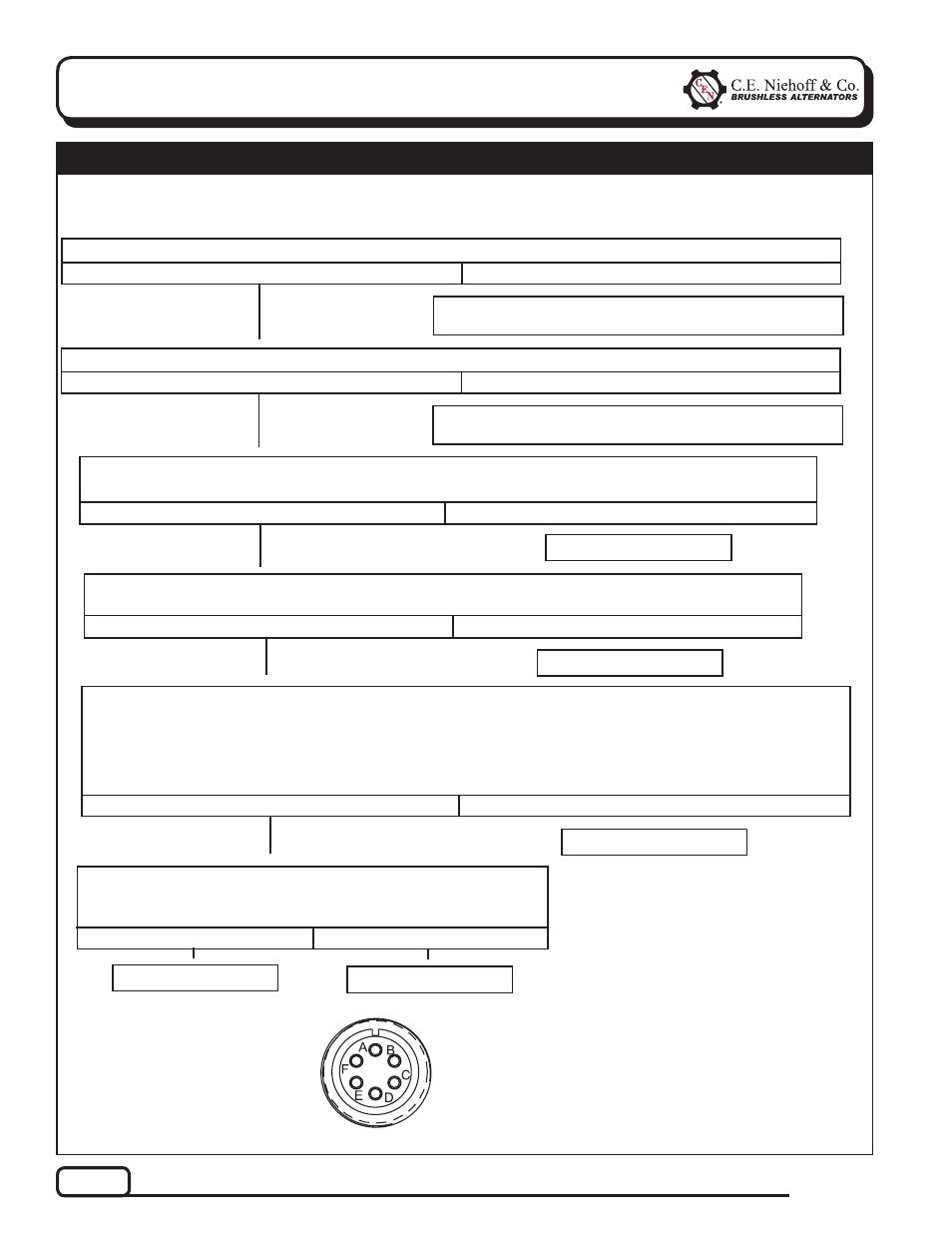
Figure 5 – Alternator-to-Regulator Harness Plug
PIN CONNECTIONS
Pin A
GND/B–
Pin B
AC
Pin C
GND/B–
Pin D
B+
Pin E
B+
Pin
F
F+
Chart 1 –
No Alternator Output –
Quick Diagnostic
With engine running: Does battery voltage exist at alternator B+ terminal and regulator E terminal?
Yes
No
Repair vehicle harness circuit to E terminal on regulator
or B+ terminal on alternator.
T
T
With key off, engine off: Unplug alternator-to-regulator harness. Connect DMM on DC volt scale across
pins A and D, and then across pins C and E in harness plug. Does battery voltage exist for both pairs?
Yes
No
With DMM on resistance scale, does the field resistance between pin F in harness plug and alterna-
torB– terminal measure about 1.6 (±0.2) ohms?
Yes
No
Alternator is defective.
T
T
Alternator is defective.
T
T
With key off, engine off: Does battery voltage exist at alternator B+ terminal?
Yes
No
Repair vehicle harness circuit to B+ terminal on alterna-
tor.
T
T
Momentarily (1 sec.) jumper pin F in harness plug to alterna-
tor B+ terminal. Touch shaft with steel tool to detect significant
magnetism. Is shaft magnetized?
Yes
No
Alternator is defective.
T
Regulator is defective.
T
Set DMM to diode test.
Check negative diodes: Connect red lead to pin B in harness plug. Connect black lead to alternator B– termi-
nal. Meter should read OL (over limit). Reverse leads. Meter should read voltage drop.
Check positive diodes: Connect red lead to pin B in harness plug. Connect black lead to alternator B+ termi-
nal. Meter should read voltage drop. Reverse leads. Meter should read OL (over limit).
Yes
No
Alternator is defective.
T
T
Remote-mounted regulator applications: Check condition of fuse in wiring harness
before troubleshooting.