C.E. Niehoff & Co. C520 Troubleshooting Guides User Manual
Page 2
Page 2
TG0048A
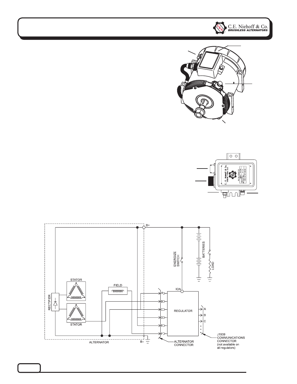
Section 1: Wiring Diagram
CEN C520 Alternator Description and
Operation
C520 14 V 300 A 3-phase alternator is internally
rectified. All windings and current-conducting compo-
nents are non-moving, so there are no brushes or slip
rings to wear out.
After engine is running, regulator receives energize
signal. Regulator monitors alternator rotation and
provides field current only when it detects alternator
shaft rotating at or above idle speed.
After regulator detects alternator rotation, it gradually
applies field current, preventing an abrupt mechani-
cal load on accessory drive system. The soft start may
take up to 20 seconds.
A2-215 regulator used with some of these units is flat
temperature compensated. A 15.5 V regulator setpoint
is available for battery isolator applications.
A2-326 regulator used with some of these units in-
cludes measurement of battery current, voltage, and
temperature for adjustment of regulator setpoint.
Figure 3 — C520 Alternator with Regulator
Figure 1 — C520 Alternator/A2-215 Regulator Features
B+
terminal
T
IGN terminal
B– terminal
T
T
Figure 2 — A2-326 Remote-Mounted Regulator Features
T
LED
LED
T
T
IGN terminal
T
Regulator receptacle
T
J1939 receptacle