C.E. Niehoff & Co. N1126-2 Filter Replacement Instructions User Manual
Page 2
1. Reference disassembly steps on page 1.
2. Remove and discard hardware and defective diode
module.
3. Clean housing surface to remove old heatsink
compound. Surface must be clean and flat before
applying new heatsink compound.
4. Apply a layer of heat sink compound, such as GC/
Waldon HSC # 10-8109 zinc oxide filled silicone or
its equivalent on the back of the new diode module
between the module and housing surface.
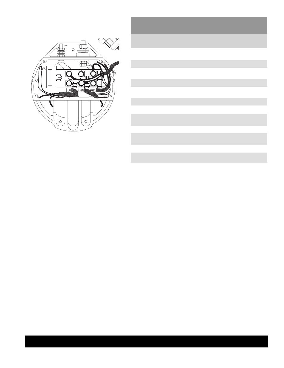
5. Install new diode module in orientation shown in
Figure 3. Stack mounting hardware on mounting
studs: nut, disc spring washer, flat washer. Torque
nuts to 12.5 Nm/9.2 lb. ft.
6. After diode module is secured in place, reference
reassembly instructions on page 1.
Diode module tests:
II0120A
Page 2 of 2
C. E. Niehoff & Co. • 2021 Lee Street • Evanston, IL 60202 Tech Services Hotline 800-643-4633
TESTED
CIRCUIT
TABLE C–4 C704 Diode Module Tests
REMOVE PHASE LEADS. USE DIODE TEST SCALE ON DMM.
REPEAT TESTS FOR EACH MODULE. SEE FIGURE C–11.
METER
(+) LEAD
CONNECTION
EXPECTED
READING
(+) side diode
(–) side diode
(+) side diode
(–) side diode
(+) side diode
(–) side diode
METER
(–) LEAD
CONNECTION
Terminal A
Terminal A
Terminal B
Terminal B
Terminal C
Terminal C
Terminal D
Terminals E & F
Terminal D
Terminals E & F
Terminal D
Terminals E & F
<1.0 volts
(fl ow)
OL (blocking)
<1.0 volts
(fl ow)
OL (blocking)
<1.0 volts
(fl ow)
OL (blocking)
Terminal A
Terminal A
Terminal B
Terminal B
Terminal C
Terminal C
Terminal D
Terminals E & F
Terminal D
Terminals E & F
Terminal D
Terminals E & F
(+) side diode
(–) side diode
(+) side diode
(–) side diode
(+) side diode
(–) side diode
OL (blocking)
<1.0 volts
(fl ow)
OL (blocking)
<1.0 volts
(fl ow)
OL (blocking)
<1.0 volts
(fl ow)
A
B
C
D
E
F
TABLE 1 Diode Module Tests
USE DIODE TEST SCALE ON DMM.
SEE FIGURE 3.
TEST
NO.
1
2
3
4
5
6
7
8
9
10
11
12
To replace diode module:
Figure 3 – Diode Module Terminal Designations