C.E. Niehoff & Co. N1126-2 Filter Replacement Instructions User Manual
N9700 filter replacement kit and diode module test
II0120A
Page 1 of 2
N1126-2 Alternator
N9700 Filter Replacement Kit and
Diode Module Test
Field Instructions
Disassembly:
1. Disconnect alternator-to-regulator harness plug at
regulator.
2. Remove and discard four screws from black cover
plate on control unit. Loosen cover to access wiring
underneath.
3. Label and disconnect three harness leads, red
(B+), green (B–), and brown (AC) from defective
filter.
4. Label three black phase leads from diode module at
filter.
5. Remove and discard six screws attaching filter to
diode
module.
6. Uncouple gray connector on harness.
7. Remove and discard filter.
8. Test diode module per Table 1, page 2.
• If defective, see diode replacement on page 2.
• If not defective, follow directions below for
reassembly.
Assembly:
NOTE: Before reassembly, make sure all ring, power,
and diode terminals are cleaned with a wire brush to
remove any conformal coating and ensure a good elec-
trical connection.
1. Put end of harness with ring terminal through hole
in cover from outside.
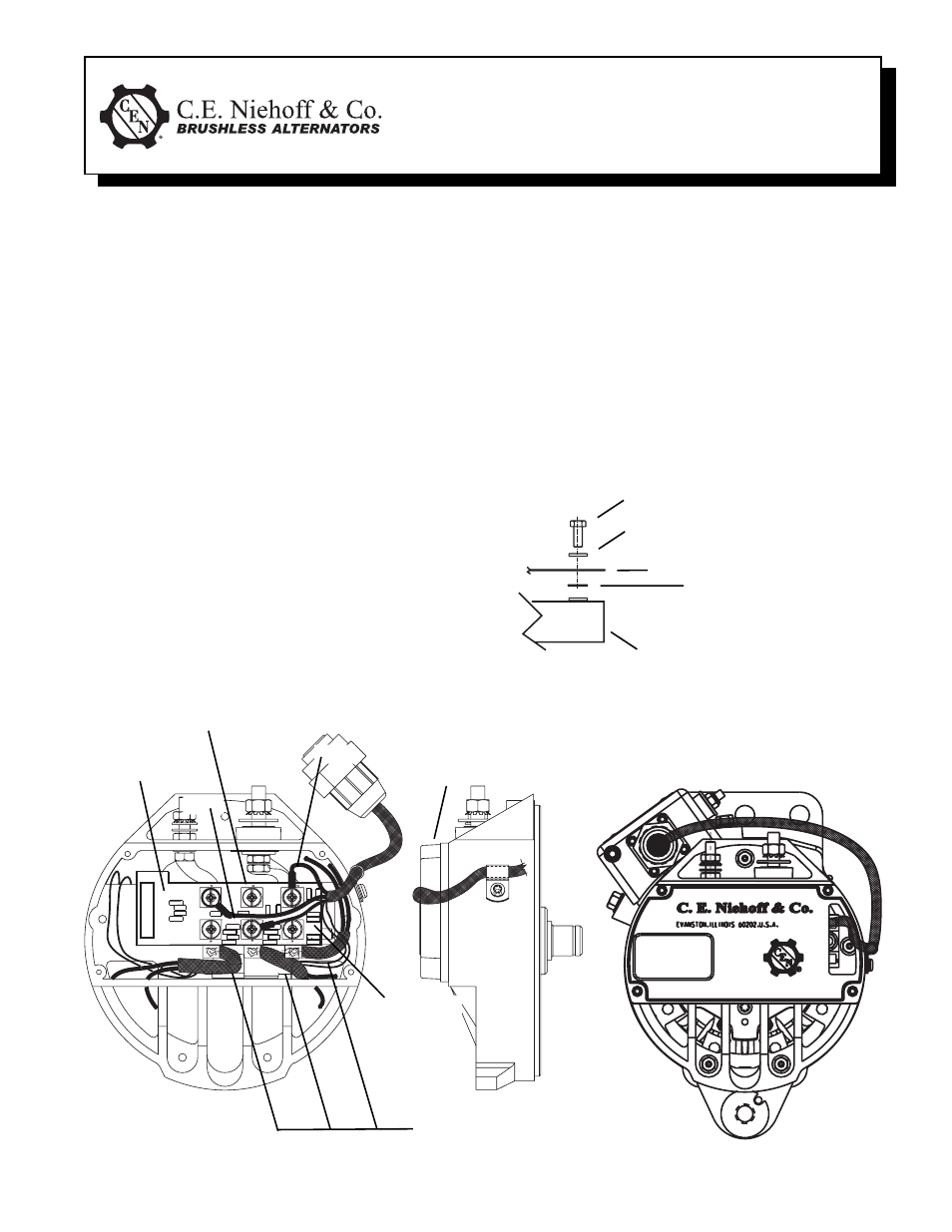
Use washer as spacer between fi lter and di-
ode module in this position only
V
Figure 2 – Replacing Filter and Black Cover Plate on N1126-2 Alternator
2. Mate two ends of gray connector.
3. Install phase leads, copper links, and spacer
washer between new filter and diode module using
new hardware. Leave fasteners loose.
4. Install screws in terminals E, A, and C. Leave
fasteners loose. See Figure 3 on page 2.
5. Using new hardware, install red harness lead
(B+) in terminal D. Install brown harness lead (AC)
in terminal B and green harness lead in terminal F.
6. Torque down all fasteners (4.6 Nm/40 lb. in.) taking
caution to ensure proper connection.
7. Replace black cover plate and torque fasteners to
2.3 Nm/20 lb. in.
8. Reconnect alternator-to-regulator harness plug at
regulator.
Filter
Black cover plate
V
V
Three phase leads
V
V
V
Diode module
Power terminal (phase lead,
copper link, or spacer washer)
Filter
Washer
Screw
V
V
V
V
V
Figure 1 – Diode Module Stacking Order
Red
V
Green
V
V
V
Brown