C.E. Niehoff & Co. C714 Alternator Retrofit/Upgrade Installation User Manual
Page 2
II0152A
Page 2 of 2
C. E. Niehoff & Co. • 2021 Lee Street • Evanston, IL 60202 Tech Services Hotline 800-643-4633
2.
A2-155 regulator is supplied separately on request
with aftermarket units.
Regulator is flat-temperature
compensated and is factory-set at lowest setting to
accommodate maintenance (8D) batteries. For other
batteries, change voltage selector switch position on
bottom of regulator. See Table 1.
When replacing A1-704, C711, or
C712 alternator, the existing regula-
tor must be replaced with A2-155
regulator. Failure to do so will result
in improper operation of unit.
Neither regulator nor alternator can
be modified to accommodate older
model regulators.
3. Install regulator on anti-drive end housing. Torque
mounting screws to 8.5 Nm/75 lb. in.
4. A2-155 regulator connections:
• Plug alternator-to-regulator harness into
regulator.
• Connect IGN terminal to ignition source through
existing switch. Torque M5 terminal nut on
regulator to 4.5 Nm/40 lb. in.
• Connect P terminal to tachometer or relay.
P terminal taps AC voltage, typically half the
charge voltage. Torque M6 terminal nut on
regulator to 4.5 Nm/40 lb. in.
5. When replacing C711 or C712 alternators, the F+
sense wire is no longer needed for the new C714
alternator. Remove F+ sense wiring from vehicle.
6. All cabling, wiring or conduit must be supported
within 305 mm/12 in. of termination on alternator.
7. Choose wire gauge capable of handling maximum
alternator output with no more than 0.2 V drop on
each leg from alternator to battery.
8. Follow vehicle manufacturer’s recommendations for
belt tension.
CAUTION
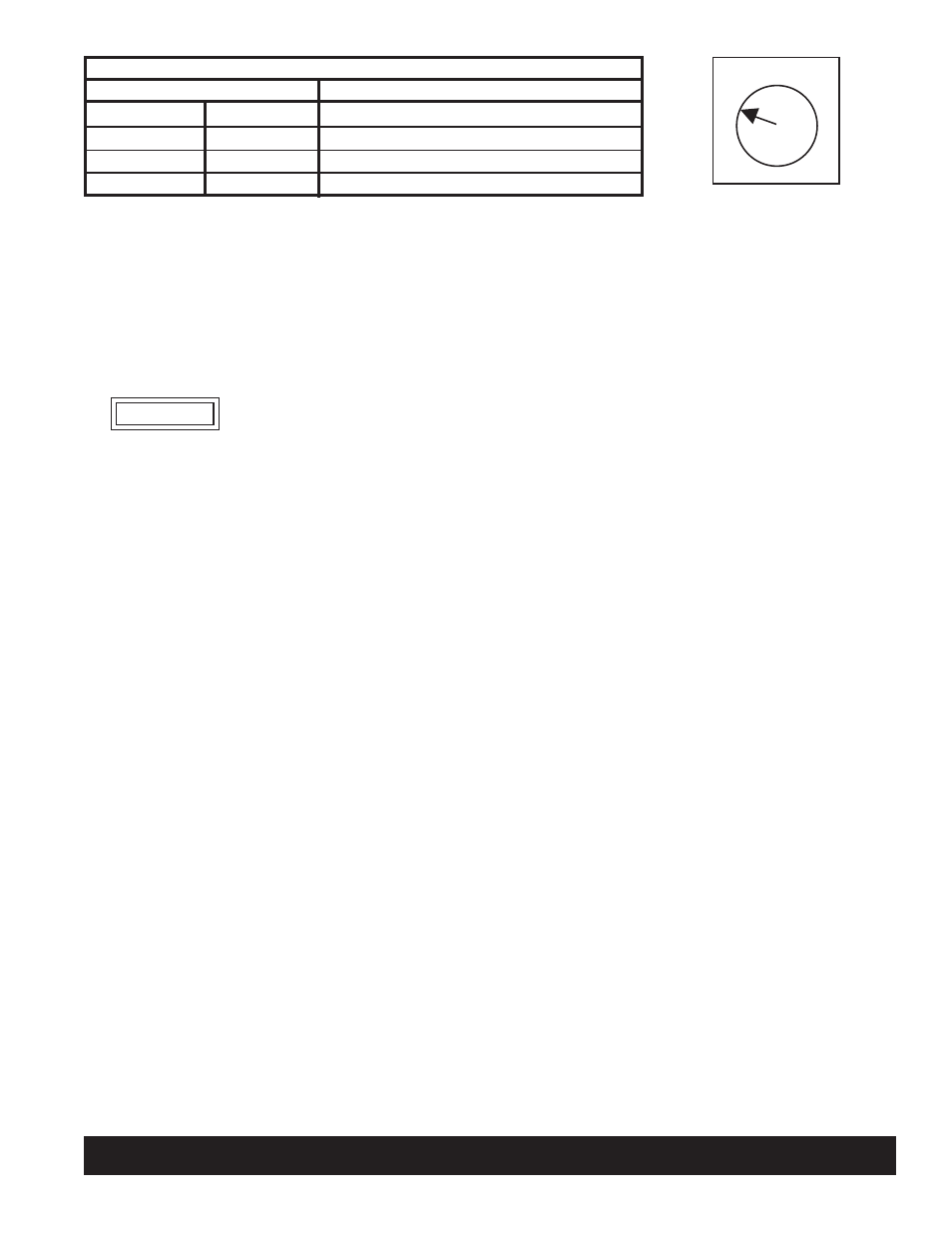
Table 1 – Voltage Select Switch Position
4 Voltage Setpoints (Fig. 2)
Position 1
14.0 V
Position 2
14.4 V
Position 3
14.8 V
Position 4
15.5 V
Battery Type
Maintenance (D Category)
Maintenance-Free (Group 31)*
Maintenance-Free (Group 31)*
Battery Isolator setpoint
*Group 31 batteries: If boiling or excessive gassing occurs with higher voltage setpoint (position 3),
change to lower voltage setpoint (position 2).
Figure 2—4 Voltage Setpoints
1
2 3
4