C.E. Niehoff & Co. C714 Alternator Retrofit/Upgrade Installation User Manual
C714 alternator, Retrofit/upgrade installation instructions
II0152A
Page 1 of 2
C714 Alternator
Retrofit/Upgrade Installation Instructions
This symbol is used to indicate presence
of hazards that can cause minor property
damage.
This symbol indicates special instructions
on installation, operation or maintenance
that are important but not related to
personal injury hazards.
CAUTION
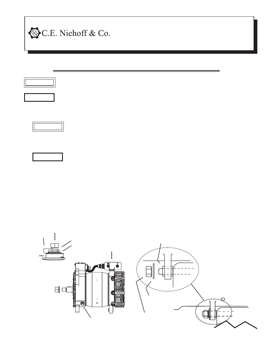
1. Install alternator as shown in Figure 1:
Slip bushing located in rear mounting
foot must be securely tightened
against alternator mounting bracket
on engine. Failure to do so can result
in broken mounting feet or broken
upper mounting bracket.
On some applications, when replacing
C712 or similar unit with C714, the
installation may require some modi-
fications to existing mounting to
accommodate new C714 alternator.
CAUTION
NOTICE
NOTICE
When replacing an existing A1-704, C711, or C712 alternator, several modifications to existing installation are required,
including replacing the pulley and regulator. READ AND FOLLOW ALL INSTRUCTIONS BELOW CAREFULLY.
a. Use hardened washers between aluminum
surfaces and bolt heads and nuts.
b. Units are shipped with shaft collar, Belleville
washer, and nut installed. Remove and discard
shaft collar.
• When replacing C714: Install existing pulley
and furnished Belleville washer. Torque fur-
nished hardware to 163 Nm/120 lb. ft.
• When replacing A1-704, C711, or C712:
Replace existing pulley with one sized
appropriately for C714 shaft and application.
Contact CEN Aftermarket Sales Department
for pulley sizing.
Figure 1—C714 Alternator Installation Details
Hardened washer
M12/0.50 Locknut –
torque to
88 Nm/65 lb. ft.
Slip bushing must be tightened against
bracket — see “CAUTION” above
Bracket
on engine
B– terminal bolt M10 x 1.5 (2 places)–
torque to 15 Nm/11 lb. ft.
M12 x1.75 bolt –
torque to 32 Nm/24 lb. ft.
Washer
Battery
output
cable
terminal
Lock washer
Insulator
Alternator B+
Terminal Stud
A2-155
Regulator