Ii72f page 2 of 2 – C.E. Niehoff & Co. C701etc/C703etc Alternator Retrofit/Upgrade Installation User Manual
Page 2
II72F
Page 2 of 2
C. E. Niehoff & Co. • 2021 Lee Street • Evanston, IL 60202 Tech Services Hotline 800-643-4633
CAUTION
9. Replace alternator drive belt if damaged or worn.
Install alternator drive belt and secure belt tension
bracket assembly. Loop alternator drive belt over
pulleys and align belt with polyvee grooves.
Make sure pulley ratio will not overspeed
alternator.
10. Belt tension guidelines shown below are a starting
point for manual and automatic belt tensioners.
•
K-section pulley: 8 grooves minimum, 10 grooves
preferred.
•
Belt wrap: 180 degree nominal. Less wrap
requires a pulley with more grooves and more
belt tension.
•
Belt tension: 80 lbs to 120 lbs nominal. More
pulley grooves permit lower belt tension.
For further questions, please contact drive belt
manufacturer.
Both too low and too high belt tension
causes premature bearing failure. Too
low belt tension causes belt slip, pulley
heating, bearing heating, and ultimately
bearing failure. Too high belt tension
increases bearing fatigue, resulting in
bearing failure.
11. Modify electrical connections to disable existing
regulator:
•
50-RD regulator – see Figure 2. Disconnect POS
lead at POS terminal on regulator and reconnect
to FLD terminal on regulator. Torque #10-24
screw to 2.3 Nm/20 lb. in.
CAUTION
Figure 2 – 50-RD Regulator Modification
Reroute this lead from POS to FLD
POS
FLD
NEG
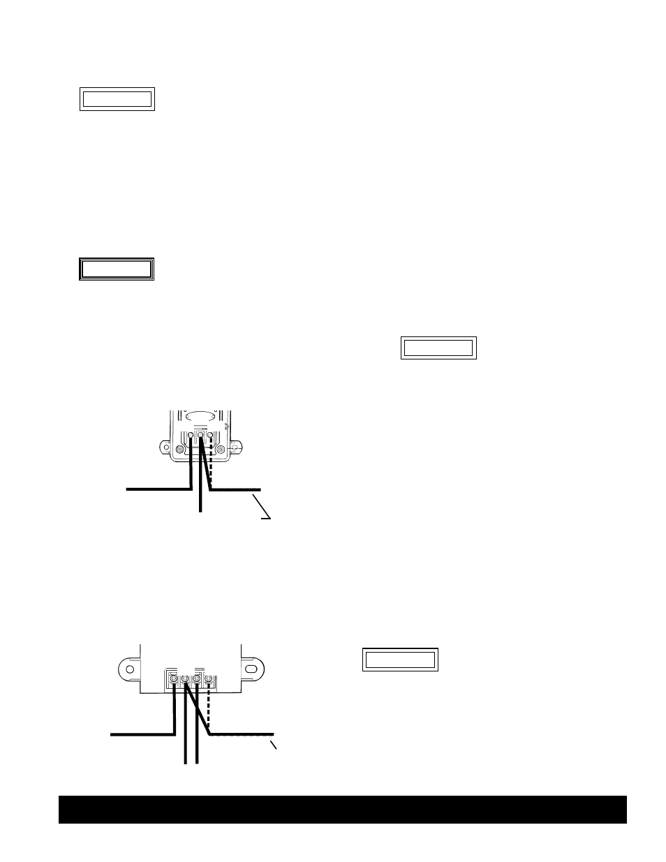
Figure 3 – 50-VR Regulator Modification
Reroute this lead
from IGN to FLD (see NOTE above)
IGN
BAT
GND
FLD
•
50-VR regulator (refer to NOTE below) – see
Figure 3. Disconnect IGN lead at IGN terminal
on regulator and reconnect to FLD terminal on
regulator. Torque screw to 1.4 – 1.7 Nm/
12 – 15 lb. in.
NOTE: For 50-VR regulators with Deutsch connec-
tor, use CEN A9-940 wiring adaptor to jump field
and ignition wires.
CAUTION
12. Make electrical connections to CEN regulator:
a. Make sure alternator-to-regulator harness plug is
secure in regulator receptacle.
b. Connect FLD lead from existing regulator to IGN
terminal on regulator, using proper ring terminal.
Torque #10-24 terminal nut to 3.4 Nm/30 lb. in.
Torque M5 terminal nut to 4.5 Nm/40 lb. in.
c. Connect P terminal to tachometer or relay lead
from vehicle. P terminal taps AC voltage, typically
half the charge voltage. Use proper ring terminal.
Torque 1/4-20 terminal nut to 3.4 Nm/30 lb. in.
Torque M6 terminal nut to 4.5 Nm/40 lb. in.
d. D+ terminal provides 28 VDC sense voltage to
multiplex controller. When connecting D+
terminal to controller through a relay, the relay
coil must be diode protected and rated for proper
voltage. Use proper ring terminal. Torque 1/4-20
terminal nut to 3.4 Nm/30 lb. in. Torque M6
terminal nut to 4.5 Nm/40 lb. in.
13. Alternator electrical connections:
a. Replace battery positive cable if damaged or worn.
Connect battery positive cable from vehicle to
alternator B+ terminal. Torque B+ terminal on
alternator to 30 Nm/22 lb. ft. Torque cable clamp
hardware to 10 Nm/90 lb. in.
B+ cable must be supported by cable
clamp within 12’’ of B+ output termi-
nal to avoid premature failure of B+
output terminal. CEN recommends
using cable clamp attached to
alternator anti-drive end housing
for support.
b. Replace ground cable if damaged or worn.
Connect ground cable from vehicle to alternator
B– terminal. Torque B– terminal on alternator
to 15 Nm/11 lb. ft.
14. Alternator output test (conduct test with fully charged
batteries):
a. Turn on 28-volt battery system and start engine.
b. Turn on all vehicle loads, including interior/exte-
rior lights and air conditioning.
c. Measure voltage at alternator. Voltage reading
should be 27.6 – 28.0 V on low setting of regula-
tor and 28.5 – 29.0 V on high setting. See CEN
Troubleshooting Guides for further information.
d. Check battery cable voltage drop. There should be
no more than 0.4 V drop on each leg from alter-
nator to battery.
e. Road test vehicle for about 20 minutes.
f. Following road test, repeat output test.
Regulators used with these alternators feature
overvoltage cutout (OVCO), which disables
alternator output in an overvoltage condition.
Restarting engine resets OVCO circuit. When
an overvoltage condition is no longer present,
alternator and regulator should operate
normally. Should a no-output condition occur,
follow above reset procedure to determine if
OVCO trip is the cause.
WARNING