C.E. Niehoff & Co. C701etc/C703etc Alternator Retrofit/Upgrade Installation User Manual
Retrofit/upgrade installation instructions, Ii72f page 1 of 2
II72F
Page 1 of 2
C701/C701A and C703/C703A
Alternators
Retrofit/Upgrade Installation Instructions
This symbol is used to indicate the presence
of hazards that can cause minor personal
injury or property damage.
CAUTION
1. Turn off battery switch or disconnect battery ground
cable.
2. Remove alternator drive belt.
3. Remove all oil lines between alternator and engine.
Plug oil line outlets with properly sized pipe or tubing
plugs. Remove oil drain hose at existing alternator and
plug opening.
4. Label wires for identification, then disconnect electri-
cal connections from existing alternator.
5. Remove alternator mounting bolts and existing alter-
nator from mounting bracket.
6. A2-213, A2-214 and A2-325 regulators are flat-temper-
ature compensated and are factory-set at lowest setting
to accommodate 8D batteries. For other batteries:
a. Change voltage selector switch position on bottom
of regulator. See Table 1 at right.
b. Re-install regulator on drive end housing. Torque
mounting screws to 8.5 Nm/75 lb. in.
7. Units are shipped with shaft collar, specific washer
and nut. Remove and discard shaft collar. Install
pulley and furnished washer. Torque nut to 162.7 Nm/
120 lb. ft. C703/C703A units: Use flange washer with
newer style pulley and plain washer in envelope with
older style pulley.
8. Install alternator:
a. Carefully place alternator on alternator mounting
bracket.
Use caution when lifting alternator
to prevent possible minor personal
injury. Use hoist along with alternator
lifting ring located on top of the
alternator.
b. Secure alternator to alternator mounting bracket.
Mounting bolts should extend 17.8/25.4 mm
(0.7/1.0 in.) into alternator mounting rail. Use four
1/2-13, grade 5 or higher mounting bolts with
lock washers (existing hardware may be suitable).
Torque mounting bolts to 88 Nm/65 lb. ft.
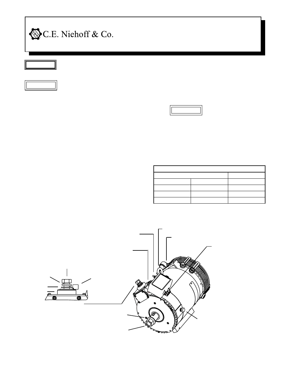
Figure 1 – C701/C701A/C703/C703A Alternator Installation Details
CAUTION
B+ terminal
C701/C701A: B– terminal 3/8-16 bolt –
torque to 15 Nm/11 lb. ft.
C703/C703A: B– terminal M10 bolt –
torque to 15 Nm/11 lb. ft.
A2-214/A2-325: D+ terminal 1/4-20 nut – torque to 3.4 Nm/30 lb. in.
A2-213: D+ terminal M6 nut – torque to 4.5 Nm/40 lb. in.
A2-214/A2-325: IGN terminal #10-24 nut – torque to 3.4 Nm/30 lb. in.
A2-213: IGN terminal M5 nut – torque to 4.5 Nm/40 lb. in.
C701/C701A: 3/4-16 nut – torque to 163 Nm/120 lb. ft.
C703/C703A: M20 x 1.5 mm flange nut or plain nut –
torque to 163 Nm/120 lb. ft.
C701/C701A: Hardened flat washer
C703/C703A: Belleville washer
C701/C701A: 1/2-13 bolt – torque to 30 Nm/22 lb. ft.
C703/C703A: M12 bolt – torque to 30 Nm/22 lb. ft.
Flat washer
Battery output
cable terminal
Lock washer
Insulator
Cable clamp
Alternator lifting ring
A2-214/A2-325: P terminal 1/4-20
nut – torque to 3.4 Nm/30 lb. in.
A2-213: P terminal M6 nut –
torque to 4.5 Nm/40 lb. in.
* Use this setpoint to maintain proper battery charge level during
shorter operating cycles.
If an extended wiring harness is supplied for use
with alternator and regulator, see separate
instructions provided with harness.
Table 1 – Regulator Voltage Selector Switch Position
Position
Battery Type
1
27.5 V
Maintenance
2
28.0 V
Maintenance*
3
28.5 V
Maintenance-Free
4
29.0 V
Maintenance-Free*
This symbol is used to indicate the presence
of hazards that can cause severe personal
injury or substantial property damage.
WARNING