MoTeC Snowmobile Plug-In ECU User Manual
Page 32
24 Appendices
MoTeC
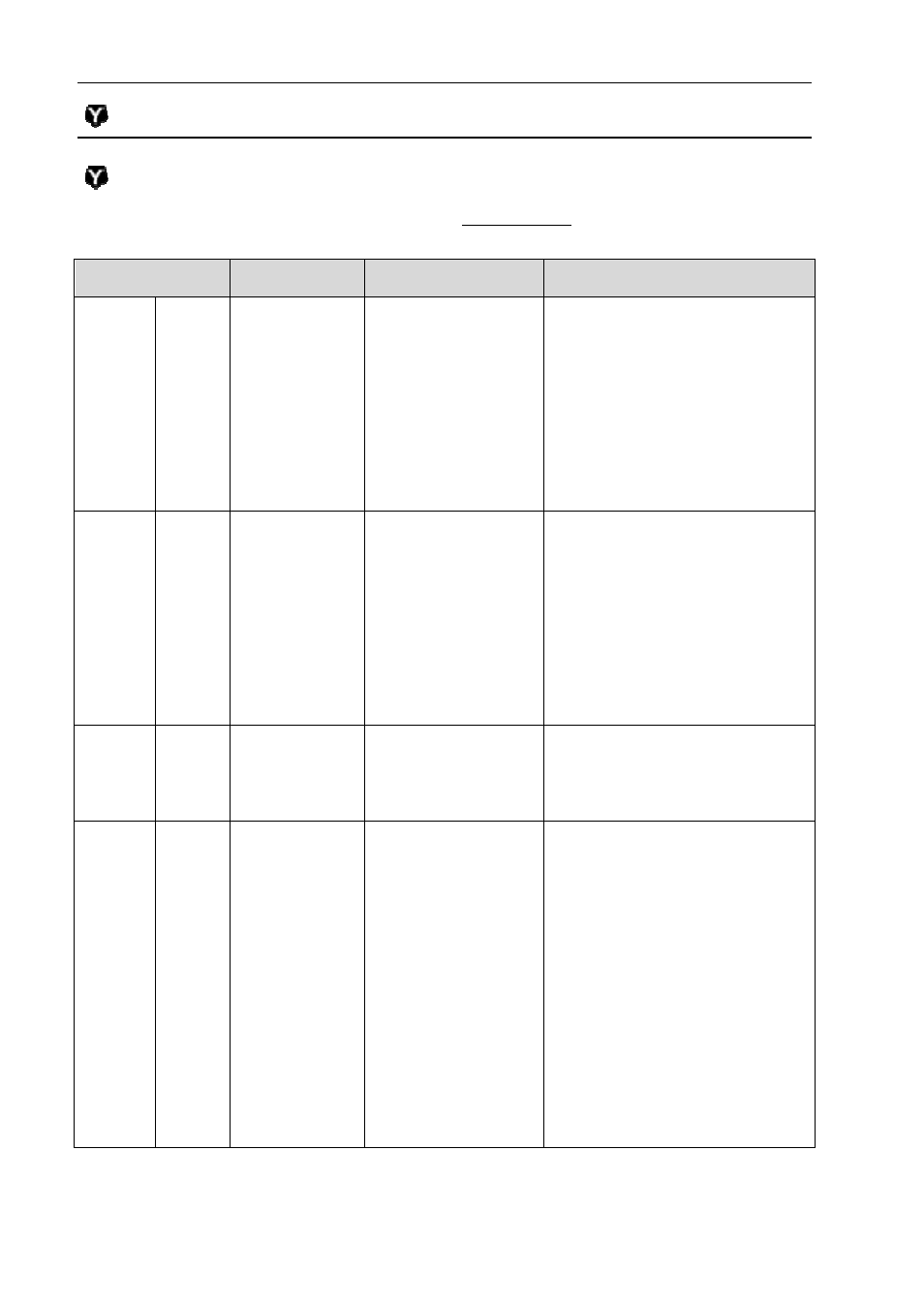
Calibration and Wiring Notes
Note 1 – Calibration Functions
The following pins are calibrated in the Base Maps with the function and
parameters as mentioned in the table.
M400 Pin
Yamaha Pin Function
Parameters
Aux2
Aux5
A01
A31
J03
J12
3: Aux Table
PWM/Switched 1
Output Mode 1
Polarity 1
Frequency 10
Minimum Duty Cycle 0
Maximum Duty Cycle 100
Hysteresis 0
Aux3
Aux4
A23
A24
R85
J11
3: Aux Table
PWM/Switched 1
Output Mode 0
Polarity 0
Frequency 10
Minimum Duty Cycle 0
Maximum Duty Cycle 100
Hysteresis 0
Aux6 A32
J10
101: Fuel Pump
Delay 3.0
Polarity 0
Output Mode 0
Aux8
A34
J04
102: Thermo Fan
On Temp 96
Off Temp 91
On Speed 0
Off Speed 0
Speed Channel 0
Time Out 0
Frequency 0
Polarity 0
Output Mode 0
Min Duty 0.00