DE-STA-CO PN500 User Manual
Page 26
24
SECTION 5: Adjustments (continued)
5.3.3. Clutch Adjustment Procedure
CAUTION: OPERATIING THE INDEXER WITH THE CLUTCH NOT ADJUSTED
CAN CAUSE IMMEDIATE AND SEVERE DAMAGE TO THE INTERNAL
COMPONENTS OF THE INDEXER.
a. Loosen cone point setscrew (number 11, Figure 14).
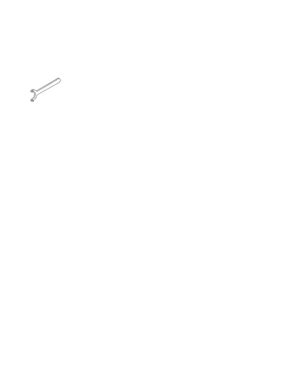
b. Insert pins of spanner (figure 15) into holes of adjusting nut (number 6,
Figure 14), and turn nut clockwise one notch in the adjusting nut. This will
tighten the clutch.
NOTE: For heavy indexing loads or clutches on large units, it may be necessary
to increase the length of the spanner wrench to gain more leverage.
If clutch has not been adjusted for a long period of time, it may be necessary
to turn the nut counter-clockwise several turns, and tap the face of housing
(number 1, Figure 14) towards the indexer with a rubber mallet to separate
(loosen) the tapers. Take note of the number of loosening turns so the adjusting
nut can be re-tightened to its original position.
c. Re-tighten setscrew (number 11, Figure 14) making sure it engages in adjusting
nut (number 6, Figure 14) to prevent damage to screw threads.
NOTE: If setscrew (number 11, Figure 14) is accidentally tightened on threaded
portion of adjusting nut (number 6, Figure 14), it will raise a burr. Failure to remove
this burr will cause shearing of threads and jamming of nut of housing (number 1,
Figure 14). To remove burr, remove setscrew (number 11, Figure 14) and rotate
adjusting nut counter-clockwise until burr is in center of tapped hole in housing
(number 1, Figure 14). Use a hand electric drill that fits freely into the tapped hole.
Drill into the adjusting nut (number 6, Figure 14) sufficiently to remove the burr.
There are (2) setscrews (number 11, Figure 14). They are positioned so one
screw is half way between the slots in the nut when the other screw engages the
slot in the nut. This is to allow for fine adjustment of the clutch. DO NOT use both
screws at the same time as one screw will not be over a slot and will cause
damage to the screw threads.
FIGURE 15