DE-STA-CO PN500 User Manual
Page 16
14
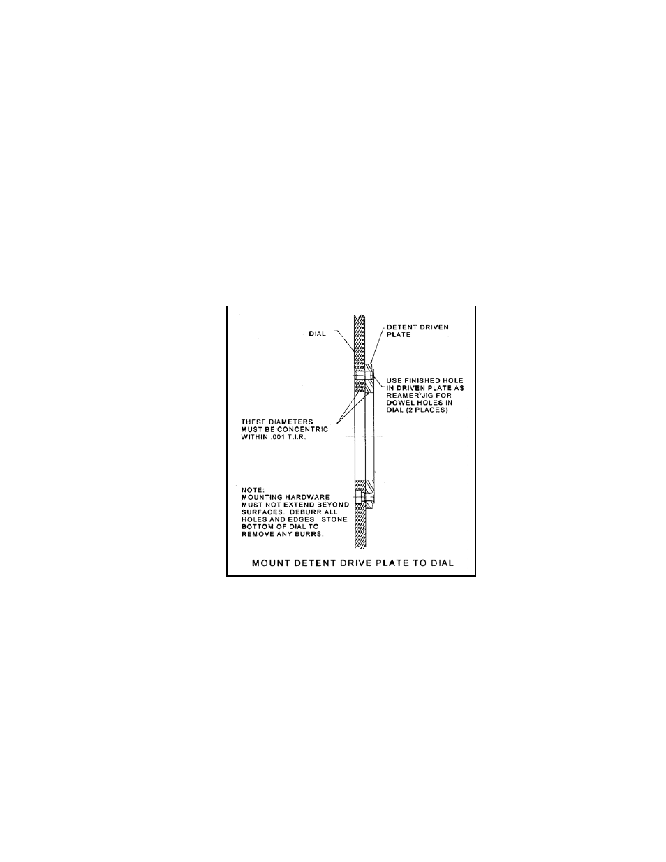
FIGURE 8
SECTION 4: Installation (continued)
4.2.1.1. Position Indexer in a dwell period of the cam (input keyway positioned as
in Figure 7 when unit is in center of dwell).
4.2.1.2. Drill and tap (4) mounting holes and (2) drilled holes into output of
Indexer as shown in Figure 7.
4.2.1.3. Rotary wire brush surfaces indicated to burnish - in bearing surfaces.
4.2.2.
Mount driven detent plate to dial.
NOTE: If dial has premachined station holes which must hold a
relationship to Indexer, verify position before following these steps.
4.2.2.1. Mount the driven detent plate of the clutch to the dial and transfer the
four 3/8 capscrew holes and two .375" diameter dowel holes.
See Figure 8.
4.2.2.2. Maintain a concentricity of .001" TIR, as indicated between the bores
in both pieces.