DE-STA-CO PN500 User Manual
Page 17
15
SECTION 4: Installation (continued)
4.2.2.3. Ream the dowel pin holes for a press fit using the hardened detent plate
as a guide for the reamer.
4.2.2.4. Assemble the driven detent plate to the dial with four 3/8-16 capscrews
and two .375" diameter dowel pins. Check that the fasteners do not
protrude on either side of the assembly. (Apply Loctite #242
Threadlocker to capscrews.)
4.2.3.
Shimming RT6-D
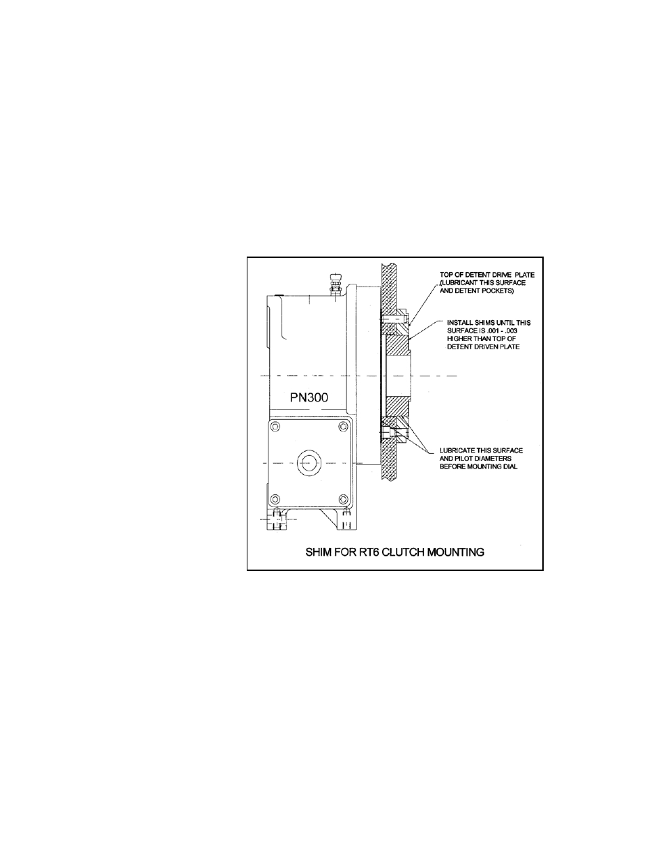
4.2.3.1. Coat the Indexer dial mounting surface and pilot with Molykote™ Grease
and mount the clutch adapter and dial/detent plate assembly.
(See Figure 9).
4.2.3.2. Rotate dial while applying downward pressure to level out excess grease.
4.2.3.3. Measure the height difference between the top of the detent driven plate
and the top of the clutch adapter. Install shims as required to raise
adapter surface .001 - .003 above top of detent driven plate. This will
ensure that the dial will rotate freely with minimum clearance.
4.2.3.4. Coat top of detent driven plate and detent pockets with Molykote™
Grease.
FIGURE 9