DE-STA-CO PN500 User Manual
Page 18
16
SECTION 4: Installation (continued)
4.2.4.
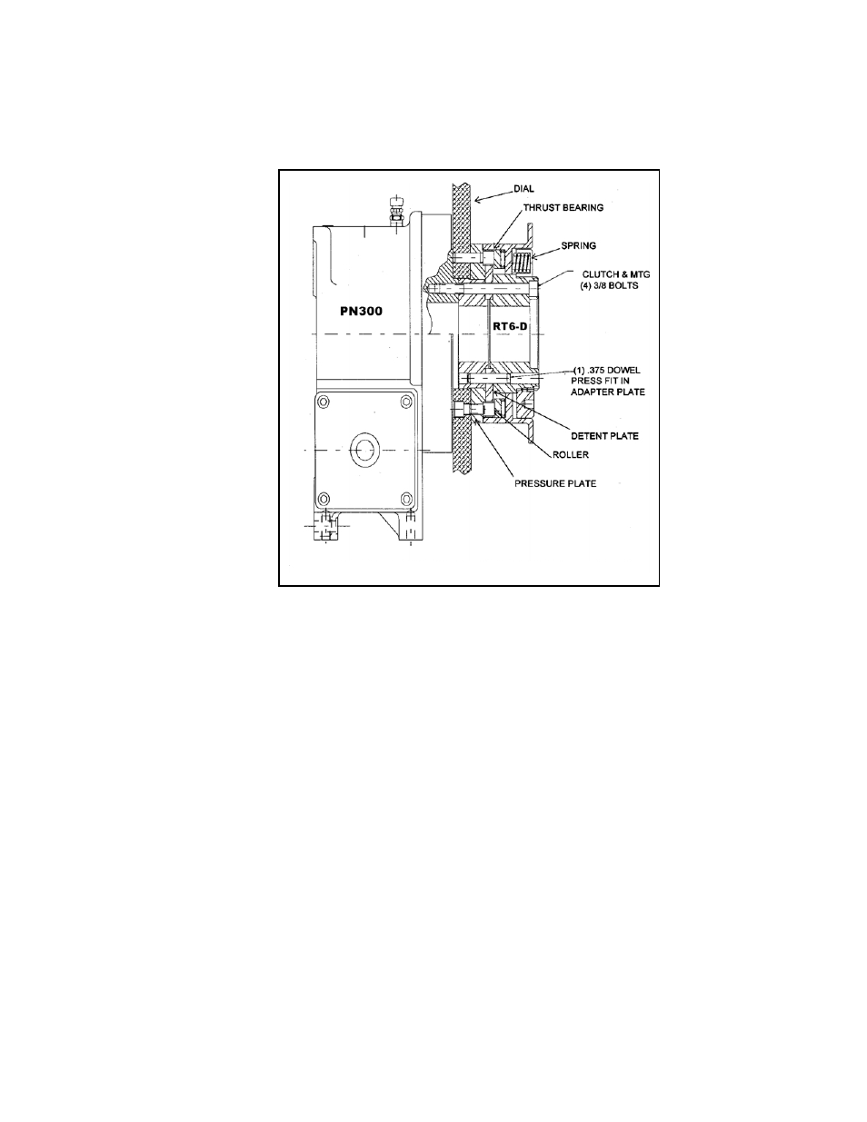
Clutch Assembly
4.2.4.1. Assemble remaining RT6-D clutch parts to PN300 unit as shown in
Figure 11 being careful to correctly align mounting holes in adjacent
parts and rotating dial to cause all rollers to seat into a detent pocket.
Coat thrust bearing and rollers with grease. (See Figure 10).
NOTE: Some parts have additional holes for use on other
applications. If dial plate has station holes, verify correct location
at this point.
4.2.4.2. Lightly snug (4) 3/8 clutch mounting bolts. Install (1) .375 dowel into
pre-machined hole to align clutch parts. Tighten clutch bolts securely.
FIGURE 10
RT6-D CLUTCH MOUNTED TO OUTPUT OF PN300