Ardware, Eatures, Onnector – Bray 70 Series SERVO PRO DeviceNET User Manual
Page 5: Iring, S70 actuator motor connector
S70 DeviceNet Servo
Installation & Maintenance Manual
2000 BRAY CONTROLS
Page 4 of 24
2.1 Hardware Features
The following are standard hardware features of the S70 DeviceNet Servo:
DeviceNet 5-position open style connector
S70 Actuator Motor connector
S70 Actuator Limit Switch connector
Feedback Potentiometer connector
Red and green calibration LED indicators
Green Power LED
Green Motor Running Open drive LED
Red Motor Running Closed drive LED
Bi-color (red / green) DeviceNet Network Status LED
2.2 Connector Wiring
2.2.1 S70 Actuator Motor Connector
The S70 Actuator Motor is connected to the S70 DeviceNet Servo motor power terminal
connector with 3 wires: Common (Black Wire), Motor Open (Blue Wire), and Motor Close (Red
Wire).
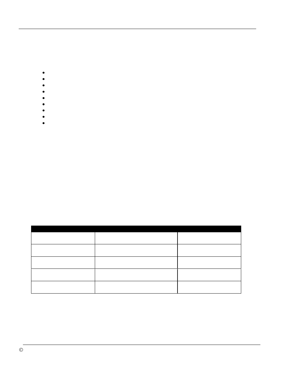
2.2.2 S70 Limit Switch Connector
If any of the Series 70 features such as the Handwheel switch (Auto / Manual Operation), torque
limit switches, or limit switches (open limit and close limit) are not used, they must be connected
to
a terminal labeled “common” for the S70 to operate.
Description
Electrical Notes
Feature Availability
Auto / Manual Handwheel
Actuator Operation
Auto Operation = Low
Manual Handwheel Engaged = Open
Standard
Closed Torque Limit
Normal Operation = Low
Limit Reached = Open
Standard
Open Travel Limit
Normal Operation = Low
Limit Reached = Open
Standard
Closed Travel Limit
Normal Operation = Low
Limit Reached = Open
Standard
Open Torque Limit
Normal Operation = Low
Limit Reached = Open
Standard
Table 1: Limit Switch Connector J6 pin description