Description, Accessories, Instrument carts – Atec Yokogawa-WT3000 User Manual
Page 19
19
DESCRIPTION
AC signals have waveforms that fluctuate repeatedly when viewed instantaneously.
Therefore, measuring the power values of AC signals requires averaging for each period in
a repeated interval, or averaging the data of several periods using a filtering process. The
WT3000 automatically selects the appropriate calculation method (one of the above two
methods) based on the data updating period. This approach ensures fast response and high
stability as suitable for the particular measurement objective.
ț
When the data updating period is 50ms, 100ms, 5s, 10s, or 20s
Measurement values are determined by applying an Average for the Synchronous Source
Period (ASSP) calculation to the sample data within the data updating period. (Note that this
excludes power integrated values WP, as well as current integrated value q in DC mode).
With ASSP, a frequency measurement circuit is used to detect the input signal period set as
the synchronous source. Sample data corresponding to an interval which is an integer
multiple of the input period are used to perform the calculation. Based on its fundamental
principles, the ASSP method allows measurement values to be obtained simply by
averaging an interval corresponding to a single period, so it is useful in cases where the
data updating period is short or when measuring the efficiency of low-frequency signals.
This method will not provide correct measurement values unless the period of the set
synchronous source signal is accurately sensed. Therefore, it is necessary to check whether
the frequency of the synchronous source signal has been accurately measured and
displayed. See the user’s manual for notes on the synchronous source signal and frequency
filter settings.
ț
When the data updating period is 250ms, 500ms, 1s, or 2s
Measurement values are determined by applying an Exponential Average for Measuring
Period (EAMP) calculation to the sample data within the data updating period. With EAMP,
the sample data are averaged by applying a digital filtering process. This method does not
require accurate detection of the input period. EAMP provides excellent measurement value
stability.
* See page 12 of the specifications for information on the relationship between the data updating
period and the lowest measurement frequency.
There are several types of power––active power, reactive power, and apparent
power. Generally, the following equations are satisfied:
Active power P = UIcosØ (1)
Reactive power Q = UIsinØ (2)
Apparent power S = UI (3)
In addition, these power values are related to each other as follows:
(Apparent power S)
2
= (Active power P)
2
+ (Reactive power Q)
2
(4)
U: Voltage RMS
I: Current RMS
Ø: Phase between current and voltage
Three-phase power is the sum of the power values in the individual phases.
These defining equations are only valid for sinewaves. In recent years, there has
been an increase in measurements of distorted waveforms, and users are
measuring sinewave signals less frequently. Distorted waveform measurements
provide different measurement values for apparent power and reactive power
depending on which of the above defining equations is selected. In addition,
because there is no defining equation for power in a distorted wave, it is not
necessarily clear which equation is correct. Therefore, three different formulas for
calculating apparent power and reactive power for three-phase four-wire
connection are provided with the WT3000.
ț
TYPE1 (method used in normal mode with older WT Series models)
With this method, the apparent power for each phase is calculated from equation (3), and reactive
power for each phase is calculated from equation (4). Next, the results are added to calculate the
power.
Active power:
P
Σ
=P1+P2+P3
Apparent power: S
Σ
=S1+S2+S3(=U1
×
I1+U2
×
I2+U3
×
I3)
Reactive power: Q
Σ
=Q1+Q2+Q3
*S1, S2, and S3 are calculated with a positive sign for the leading phase and a negative sign for the lagging phase.
ț
TYPE2
The apparent power for each phase is calculated from equation (3), and the results are added together
to calculate the three-phase apparent power (same as in TYPE1). Three-phase reactive power is
calculated from three-phase apparent power and three-phase active power using equation (4).
Active power:
P
Σ
=P1+P2+P3
Apparent power: S
Σ
=S1+S2+S3(=U1
×
I1+U2
×
I2+U3
×
I3)
Reactive power:
ț
TYPE3 (method used in harmonic measurement mode with WT1600 and PZ4000)
This is the only method in which the reactive power for each phase is directly calculated using
equation (2). Three-phase apparent power is calculated from equation (4).
Active power:
P
Σ
=P1+P2+P3
Apparent power:
Reactive power: Q
Σ
=Q1+Q2+Q3
Automatically select the appropriate calculation for each data updating period
Selecting formulas for calculating apparent power and reactive power
Q
Σ
=
S
Σ
2
-P
Σ
2
S
Σ
=
P
Σ
2
+Q
Σ
2
(=
(U1
×
I1)
2
-P1
2
+
(U2
×
I2)
2
-P2
2
+
(U3
×
I3)
2
-P3
2
500
Ч
560
Ч
705 mm (WDH)
/A: Keyboard and mouse mount
701960
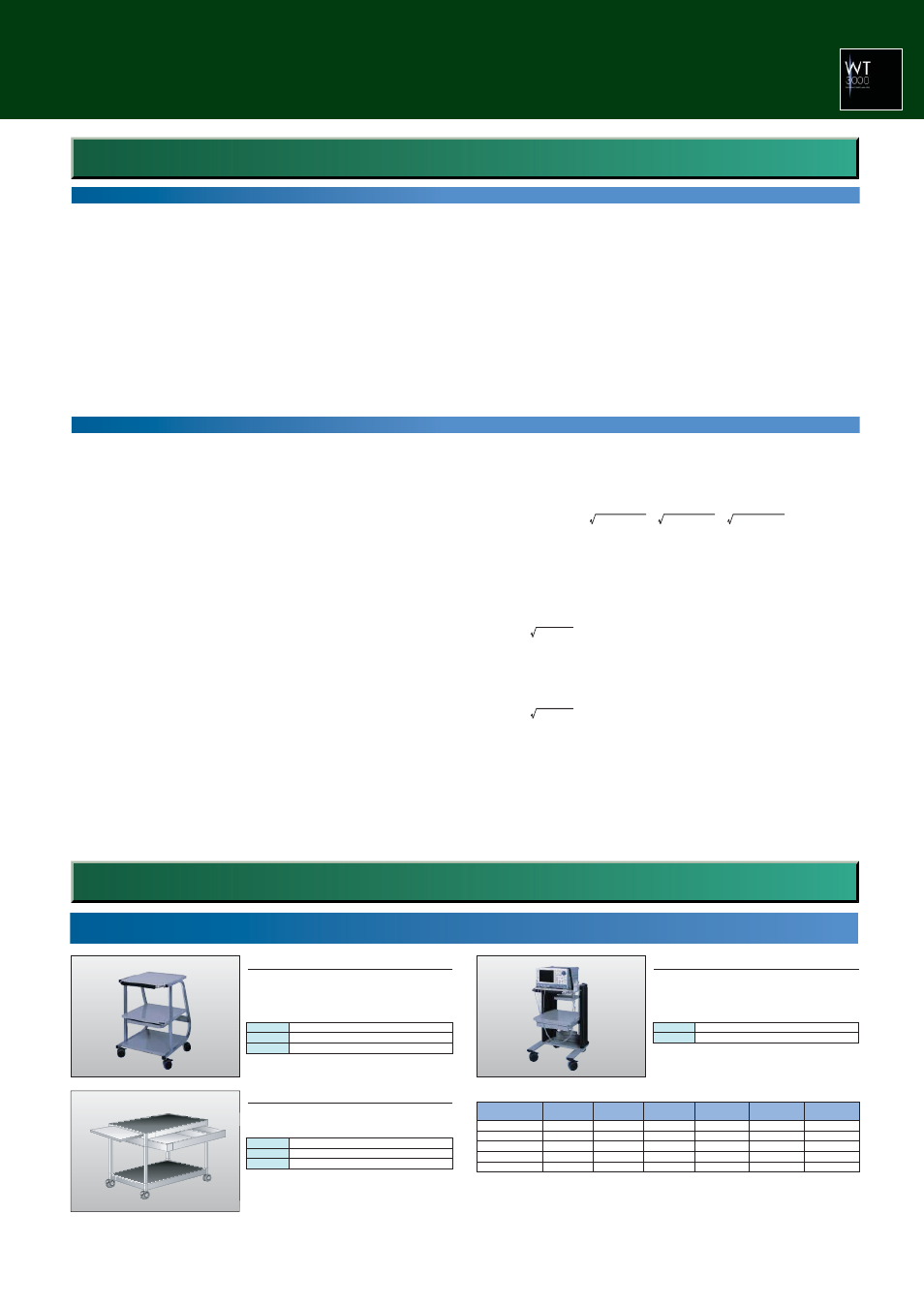
Compact Instrument Cart
570
Ч
580
Ч
839 mm (WDH)
/A: Keyboard and mouse mount
701961
Deluxe Instrument Cart
467
Ч
693
Ч
713 mm (WDH)
701962
All-purpose Instrument Cart
í External dimensions of Yokogawa power meters
(excluding protrusions)
WT3000/WT1800
WT1600
WT210/WT310
WT230/WT330
PZ4000
*1 The back-side inputs protrude beyond the back shelves of the mounts.
426
426
213
213
426
177
177
88
132
177
450
400
379
379
450
Width (mm)
Height (mm)
Depth (mm)
✓
✓
✓
✓
✓
*1
✓
✓
✓
✓
✓
*1
✓
✓
✓
✓
✓
*1
Compact mount
701960
Deluxe mount
701961
General-purpose
mount 701962
Top shelf
Middle shelf
Bottom shelf
Equipment not exceeding 450 (W)
×
450 (D)
×
300 (H) mm
Equipment not exceeding 450 (W)
×
450 (D)
×
300 (H) mm
Equipment not exceeding 450 (W)
×
450 (D)
×
240 (H) mm
* W: Width D: Depth H: Height
Maximum load: 20 kg on each shelf
Top shelf
Bottom shelf
Equipment not exceeding 450 (W)
×
450 (D)
×
400 (H) mm
Equipment not exceeding 450 (W) x 450 (D)
×
400 (H) mm
* W: Width D: Depth H: Height
Maximum load: 50 kg on each shelf
*The photo shows the mount holding a DL7400.
Top shelf
Drawer
Slide table
Equipment not exceeding 457 (W)
×
683 (D) mm
Equipment not exceeding 610 (W)
×
380 (D) mm
Equipment not exceeding 380 (W)
×
440 (D) mm
* W: Width D: Depth
Maximum load: 50 kg on each shelf
* These mount do not conform to CE marking.
Accessories
Instrument Carts.