Atec Yokogawa-WT3000 User Manual
Page 17
17
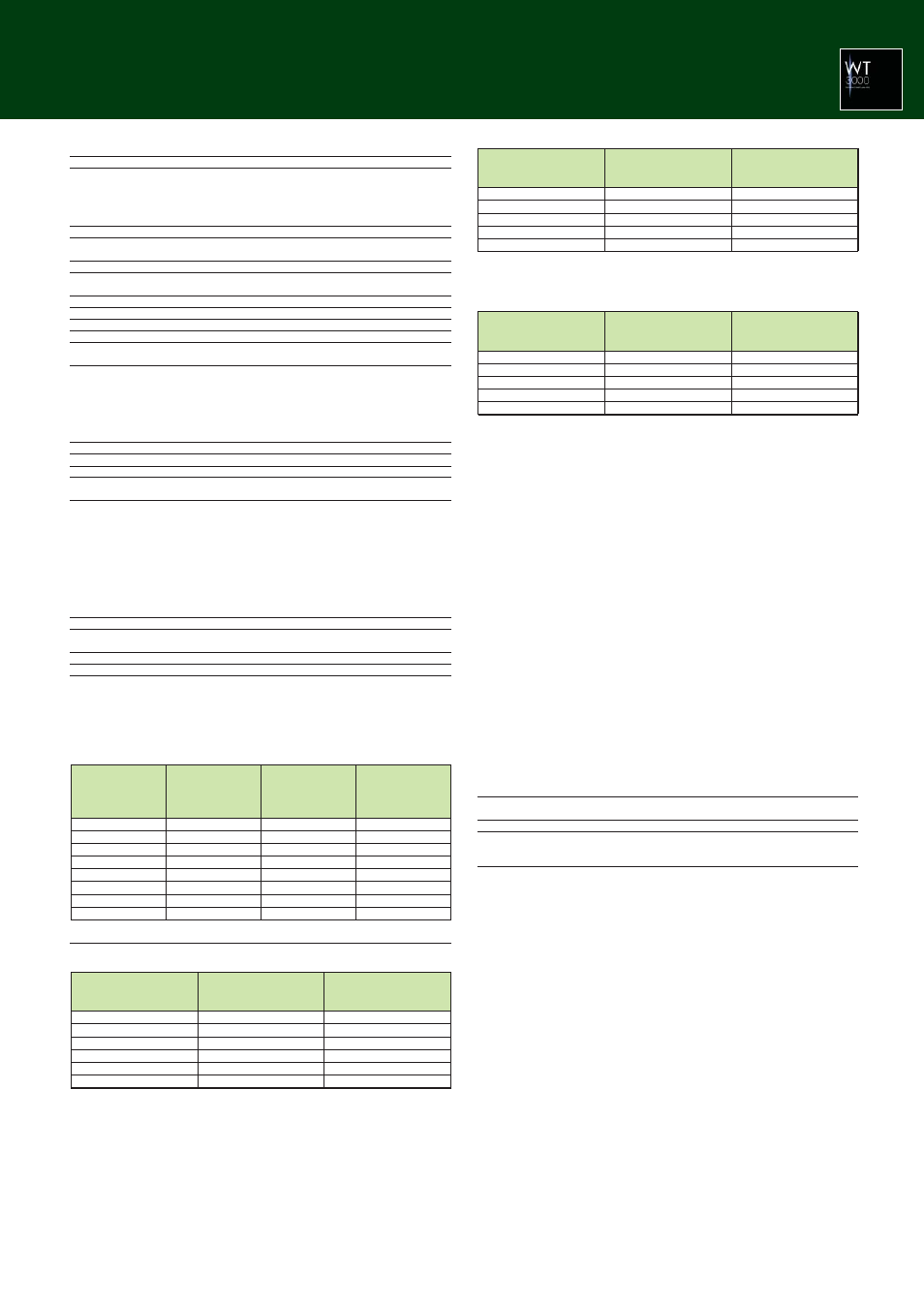
Fundamental
the PLL Source
(Hz)
10 to 20
20 to 40
40 to 55
55 to 75
75 to 150
150 to 440
440 to 1100
1100 to 2600
Sample Rate
(S/s)
f
×
3000
f
×
1500
f
×
900
f
×
750
f
×
450
f
×
360
f
×
150
f
×
60
Window Width against
the FFT Data Length
(Frequency of the
Fundamental Wave)
3
6
10
12
20
25
60
150
Upper Limit of the
Measured Order
100
100
100
100
50
15
7
3
On models with the advanced computation (/G6) option
Frequency
10 Hz
Ϲ
f
Ͻ
30 Hz
30 Hz
Ϲ
f
Ϲ
66 Hz
66 Hz
Ͻ
f
Ϲ
440 Hz
440 Hz
Ͻ
f
Ϲ
1 kHz
1 kHz
Ͻ
f
Ϲ
2.5 kHz
2.5 kHz
Ͻ
f
Ϲ
3.5 kHz
Voltage and Current
±
(reading error + measurement
range error)
0.25% of reading + 0.3% of range
0.2% of reading + 0.15% of range
0.5% of reading + 0.15% of range
1.2% of reading + 0.15% of range
2.5% of reading + 0.15% of range
8% of reading + 0.15% of range
Power
±
(reading error + measurement
range error)
0.5% of reading + 0.4% of range
0.4% of reading + 0.15% of range
1.2% of reading + 0.15% of range
2% of reading + 0.15% of range
6% of reading + 0.2% of range
16% of reading + 0.3% of range
• When the line filter (5.5 kHz) is ON
Frequency
10 Hz
Ϲ
f
Ͻ
30 Hz
30 Hz
Ϲ
f
Ϲ
440 Hz
440 Hz
Ͻ
f
Ϲ
2.5 kHz
2.5 kHz
Ͻ
f
Ϲ
5 kHz
5 kHz
Ͻ
f
Ϲ
7.8 kHz
Voltage and Current
±
(reading error + measurement
range error)
0.25% of reading + 0.3% of range
0.2% of reading + 0.15% of range
1% of reading + 0.15% of range
2% of reading + 0.15% of range
3.5% of reading + 0.15% of range
Power
±
(reading error + measurement
range error)
0.45% of reading + 0.4% of range
0.4% of reading + 0.15% of range
2% of reading + 0.2% of range
4% of reading + 0.2% of range
6% of reading + 0.2% of range
• When the line filter (50 kHz) is ON
Frequency
10 Hz
Ϲ
f
Ͻ
30 Hz
30 Hz
Ϲ
f
Ϲ
440 Hz
440 Hz
Ͻ
f
Ϲ
2.5 kHz
2.5 kHz
Ͻ
f
Ϲ
5 kHz
5 kHz
Ͻ
f
Ϲ
7.8 kHz
Voltage and Current
±
(reading error + measurement
range error)
0.15% of reading + 0.3% of range
0.1% of reading + 0.15% of range
0.6% of reading + 0.15% of range
1.6% of reading + 0.15% of range
2.5% of reading + 0.15% of range
Power
±
(reading error + measurement
range error)
0.25% of reading + 0.4% of range
0.2% of reading + 0.15% of range
1.2% of reading + 0.2% of range
3.2% of reading + 0.2% of range
5% of reading + 0.2% of range
• When the line filter is OFF
• FFT Function Specifications
Item
Specifications
Computed source
Voltage, current, active power, and reactive power of each input
element.
Active power and reactive power of an
Σ
wiring unit.
Torque and speed signals (analog input) of motor input (option).
Type
PS (power spectrum)
Number of computations Two computations (FFT1 and FFT2)
Maximum frequency of
100 kHz
analysis
Number of points
20,000 points or 200,000 points
Measurement period for 100 ms or 1 s
the computation
Frequency resolution
10 Hz or 1 Hz
Window function
Rectangular, Hanning, or Flattop
Anti-aliasing filter
Set using a line filter (OFF, 500 Hz, 5.5 kHz, or 50 kHz).
Sampling clock
Fixed to 200 kHz
Display update
Data update rate or (measurement period of the FFT + FFT
computing time), whichever is longer
* The measurement period is 1 s when the number of FFT points is 200 k (when the frequency
resolution is 1 Hz).
The measurement period is 100 ms when the number of FFT points is 20 k (when the
frequency resolution is 10 Hz).
• Harmonic Measurement in Normal Measurement
Item
Specifications
Measured source
All installed elements
Format
PLL synchronization method
Frequency range
Range in which the fundamental frequency of the PLL source is 10
Hz to 2600 Hz
PLL source
• Select the voltage or current of each input element (external
current sensor range is greater than or equal to 500 mV) or the
external clock (Ext Clk).
• Input level
Greater than or equal to 50% of the measurement range rating
when the crest factor is 3
Greater than or equal to 100% of the measurement range rating
when the crest factor is 6
• Turn the frequency filter ON when the fundamental frequency is
less than or equal to 440 Hz.
FFT data length
9000
FFT processing word
32 bits
length
Window function
Rectangular
Anti-aliasing filter
Set using a line filter (5.5 kHz or 50 kHz).
Note)
To measure and display harmonic data requires a data update rate of 500 ms or
more
Sample rate (sampling frequency), window width, and upper limit of measured order during
PLL synchronization
Accuracy
If the fundamental frequency is between 1 kHz and 2.6 kHz, add 0.5% of reading to the
voltage and current accuracy and 1% of reading to the power accuracy when the frequency
exceeds 1 kHz.
If the fundamental frequency is between 1 kHz and 2.6 kHz, add 0.5% of reading to the
voltage and current accuracy and 1% of reading to the power accuracy when the frequency
exceeds 1 kHz.
If the fundamental frequency is between 1 kHz and 2.6 kHz, add 0.5% of reading to the
voltage and current accuracy and 1% of reading to the power accuracy when the frequency
exceeds 1 kHz.
However, all the items below apply to all tables.
• When averaging is ON, the averaging type is EXP, and the attenuation constant is greater
than or equal to 8.
• When the crest factor is set to 3
• When
λ
(power factor) = 1
• Power exceeding 440 Hz are reference value.
• For external current sensor range, add 0.2 mV to the current accuracy and add (0.2 mV/
external current sensor range rating)
×
100% of range to the power accuracy.
• For 30A direct current input range, add 0.2 mA to the current accuracy and add (0.2 mA/
direct current input range rating)
×
100% of range to the power accuracy.
• For 2A direct current input range, add 2
µ
A to the current accuracy and add (2
µ
A/direct
current input range rating)
×
100% of range to the power accuracy.
• For n
th
order component input, add {n/(m+1)}/50% of (the n
th
order reading) to the n+m
th
order and n-m
th
order of the voltage and current, and add {n/(m+1)}/25% of (the n
th
order
reading) to the n+m
th
order and n-m
th
order of the power.
• Add (n/500)% of reading to the nth component of the voltage and current, and add (n/
250)% of reading to the n
th
component of the power.
• Accuracy when the crest factor is 6: The same as when the range is doubled for crest
factor 3.
• The accuracy guaranteed range by frequency and voltage/current is the same as the
guaranteed range of normal measurement.
If the amplitude of the high frequency component is large, influence of approximately 1%
may appear in certain orders. The influence depends on the size of the frequency
component. Therefore, if the frequency component is small with respect to the range rating,
this does not cause a problem.
• Waveform Sampling Data Saving Function
Parameters
Voltage waveform, current waveform, analog input waveform of
torque and speed waveform calculation, FFT performing data
Data type
CSV format, WVF format
Storage
PCMCIA, USB memory (/C5 option)
* Waveform calculation function (MATH) cannot be used with FFT
calculation at the same time.