Atec Yokogawa-WT3000 User Manual
Page 15
15
Voltage(V)
Current (A)
Item
difference
3P3W
→
3V3A
DELTA
→
STAR
STAR
→
DELTA
difference
3P3W
→
3V3A
DELTA
→
STAR
STAR
→
DELTA
Specifications
̅
U1: Differential voltage determined by computation u1 and u2
̅
U1: Line voltage that are not measured but can be computed for a three-
phase, three-wire system
̅
U1,
̅
U2,
̅
U3: Line voltage that can be computed for a three phase,
three-wire (3V3A) system
̅
U1,
̅
U2,
̅
U3: Neutral line voltage that can be computed for a three-
phase, four-wire system
̅
I1: Differential current determined by computation
Phase current that are not measured but can be computed
Neutral line current
Neutral line current
Fundamental
Frequency of the
PLL Source
(Hz)
10 to 20
20 to 40
40 to 55
55 to 75
75 to 150
150 to 440
440 to 1100
1100 to 2600
Sample Rate
(S/s)
f
×
3000
f
×
1500
f
×
900
f
×
750
f
×
450
f
×
360
f
×
150
f
×
60
Window Width against
the FFT Data Length
(Frequency of the
Fundamental Wave)
3
6
10
12
20
25
60
150
Upper Limit of the
Measured Order
100
100
100
100
62
62
62
20
PLL source synchronization method
Fundamental
Frequency of the
PLL Source
(Hz)
0.1 to 66
Sample Rate
(S/s)
f
×
3000
Window Width against
the FFT Data Length
(Frequency of the
Fundamental Wave)
3
Upper Limit of the
Measured Order
100
External sampling clock method
Approx. 7.5 V
5.0V
2.5V
0.5V
0.5Hz 1Hz
10Hz 100Hz
10kHz 100kHz 1MHz
Displayed value
1kHz
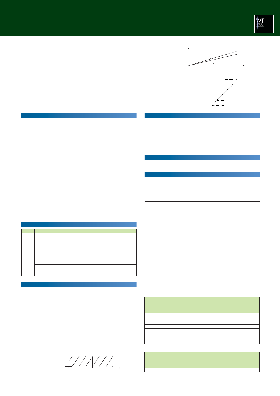
D/A output
t
o
Approx. 7.0 V
5.0V
0
Integration time
t0:Rated time of integrated D/A output for manual integration mode,
specified time of timer for normal integration and repetitive
(continuous) integration modes
D/A output
Input that is 140% of the rating
Rated input
Note that PF and deg are not output beyond the range of
±
5.0 V.
If an error occurs, approximately
±
7.5 V are output.
0
°
to 360
°
are output at 0 to 5.0 V; LAG180
°
to LEAD180
°
are
output at -5.0 V to 5.0 V.
Displayed Value
140%
100%
0%
–100%
–140%
Output
Approx. 7.0 V
5.0 V
0 V
–5.0 V
Approx. –7.0 V
Approx. 7.5 V
Approx. 7.0 V
5.0 V
0
–5.0 V
–100
100
–140
140
Approx. –7.0 V
Approx. –7.5 V
Displayed value [%]
D/A output
Integrated Value
Other Items
Built-in Printer (/B5 Optional)
Printing method
Thermal line-dot
Dot density
8 dots/mm
Paper width
112 mm
Effective recording width
104 mm
Recorded information
Screenshots, list of measured values, harmonic bar graph
printouts, settings
Auto print function
Measured values are printed out automatically.
However, auto print function can’t use in combination with
store function.
RGB Video Signal (VGA) Output Section (/V1 Optional)
Connector type
15-pin D-Sub (receptacle)
Output format
VGA compatible
Advanced Calculation (/G6 optional)
• Wide Bandwidth Harmonic Measurement
Item
Specifications
Measured source
All installed elements
Format
PLL synchronization method (when the PLL source is not set to
Smp Clk) or external sampling clock method (when the PLL source
is set to Smp Clk)
Frequency range
• PLL synchronization method
Fundamental frequency of the PLL source is in the range of 10
Hz to 2.6 kHz.
• External sampling clock method
Input a sampling clock signal having a frequency that is 3000
times the fundamental frequency between 0.1 Hz and 66 Hz of
the waveform on which to perform harmonic measurement. The
input level is TTL. The input waveform is a rectangular wave with
a duty ratio of 50%.
PLL source
• Select the voltage or current of each input element (external
current sensor range is greater than or equal to 500 mV) or the
external clock (Ext Clk or Smp Clk).
• Input level
Greater than or equal to 50% of the measurement range rating
when the crest factor is 3
Greater than or equal to 100% of the measurement range rating
when the crest factor is 6
• Turn the frequency filter ON when the fundamental frequency is
less than or equal to 440 Hz.
FFT data length
9000
FFT processing word
32 bits
length
Window function
Rectangular
Anti-aliasing filter
Set using a line filter (OFF, 500 Hz, 5.5 kHz, or 50 kHz).
Sample rate (sampling frequency), window width, and upper limit of measured order
Revolution signal, torque signal
• When revolution and torque signals are DC voltage (analog input)
Connector type
Insulated BNC connector
Input range
1 V,2 V,5 V,10 V,20 V
Effective input range
0%–
±
110% of measurement range
Input resistance
Approximately 1 M
Ω
Continuous maximum allowed input
±
22 V
Continuous maximum common mode voltage
±
42 Vpeak or less
Accuracy
±
(0.1% of reading+0.1% of range)
Temperature coefficient
±
0.03% of range/
°
C
• When revolution and torque signals are pulse input
Connector type
Insulated BNC connector
Frequency range
2 Hz–200 kHz
Amplitude input range
±
12 Vpeak
Effective amplitude
1 V (peak-to peak) or less
Input waveform duty ratio
50%, square wave
Input resistance
Approximately 1 M
Ω
Continuous maximum common mode voltage
±
42 Vpeak or less
Accuracy
±
(0.05% of reading+1mHz)
Added Frequency Measurement (/FQ Optional)
Device under measurement
Select up to two frequencies of the voltage or current input to
the input elements for measurement. If the frequency option (/
FQ) is installed, the frequencies of the voltages and currents
being input to all input elements can be measured.
Measurement method
Reciprocal method
Measurement range
Data Update Rate
Measuring Range
50ms
45Hz
Ϲ
f
Ϲ
1MHz
100ms
25Hz
Ϲ
f
Ϲ
1MHz
250ms
10Hz
Ϲ
f
Ϲ
500kHz
500ms
5Hz
Ϲ
f
Ϲ
200kHz
1s
2.5Hz
Ϲ
f
Ϲ
100kHz
2s
1.5Hz
Ϲ
f
Ϲ
50kHz
5s
0.5Hz
Ϲ
f
Ϲ
20kHz
10s
0.25Hz
Ϲ
f
Ϲ
10kHz
20s
0.15Hz
Ϲ
f
Ϲ
5kHz
Accuracy
±
0.05% of reading
When the input signal levels are greater than or equal to 25
mV (current external sensor input), 1.5mA (current direct input
of 2A input element) and 150 mA (current direct input of 30A
input element) respectively, and the signal is greater than or
equal to 30% (0.1 Hz–440 Hz, frequency filter ON), 10% (440
Hz–500 kHz), or 30% (500 kHz–1 MHz) of the measurement
range. However, when the measuring frequency is smaller or
equal to 2 times of above lower frequency, the input signal is
greater than or equal to 50%.
Add 0.05% of reading when current external input is smaller
than or equal to 50 mV input signal level for each is double for
crest factor 6.
Delta Calculation Function (/DT Optional)
D/A Output (/DA Optional)
D/A conversion resolution
16 bits
Output voltage
±
5 V FS (max. approximately
±
7.5 V) for each rated value
Update rate
Same as the data update rate on the main unit.
Number of outputs
20 channels (each channel can be set separately)
Accuracy
±
(accuracy of a given measurement function + 0.1% of FS)
FS = 5V
D/A zoom
Setting maximum and minimum values.
Continuous maximum common mode voltage
±
42Vpeak or less
Minimum load
100 k
Ω
Temperature coefficient
±
0.05% of FS/
°
C
Remote control
EXT START, EXT STOP, EXT RESET, EXT HOLD, EXT
SINGLE and EXT PRINT (all input signal) / INTEG BUSY
(output signal) Requires /DA option
Frequency (Simplified Figure Below)