Precision power analyzer wt3000 – Atec Yokogawa-WT3000 User Manual
Page 16
16
Precision Power Analyzer WT3000
Frequency
0.1 Hz
Ϲ
f
Ͻ
10 Hz
10 Hz
Ϲ
f
Ͻ
30 Hz
30 Hz
Ϲ
f
Ϲ
440 Hz
440 Hz
Ͻ
f
Ϲ
1 kHz
1 kHz
Ͻ
f
Ϲ
5 kHz
5 kHz
Ͻ
f
Ϲ
10 kHz
Voltage and Current
±
(reading error + measurement
range error)
0.25% of reading + 0.3% of range
0.25% of reading + 0.3% of range
0.3% of reading + 0.05% of range
0.7% of reading + 0.05% of range
0.7% of reading + 0.05% of range
3.0% of reading + 0.05% of range
Power
±
(reading error + measurement
range error)
0.45% of reading + 0.4% of range
0.45% of reading + 0.4% of range
0.45% of reading + 0.1% of range
1.4% of reading + 0.1% of range
1.4% of reading + 0.15% of range
6% of reading + 0.15% of range
• When the line filter (50 kHz) is ON
Frequency
0.1 Hz
Ϲ
f
Ͻ
10 Hz
10 Hz
Ϲ
f
Ͻ
30 Hz
30 Hz
Ϲ
f
Ͻ
66 Hz
Voltage and Current
±
(reading error +
measurement range error)
0.7% of reading + 0.3% of range
0.7% of reading + 0.3% of range
0.7% of reading + 0.05% of range
Power
±
(reading error + measurement
range error)
1.4% of reading + 0.4% of range
1.4% of reading + 0.4% of range
1.4% of reading + 0.1% of range
• When the line filter (500 Hz) is ON
Frequency
0.1 Hz
Ϲ
f
Ͻ
10 Hz
10 Hz
Ϲ
f
Ͻ
30 Hz
30 Hz
Ϲ
f
Ϲ
66 Hz
66 Hz
Ͻ
f
Ϲ
440 Hz
440 Hz
Ͻ
f
Ϲ
1 kHz
1 kHz
Ͻ
f
Ϲ
2.5 kHz
2.5 kHz
Ͻ
f
Ϲ
3.5 kHz
Voltage and Current
±
(reading error + measurement
range error)
0.25% of reading + 0.3% of range
0.25% of reading + 0.3% of range
0.3% of reading + 0.05% of range
0.6% of reading + 0.05% of range
1% of reading + 0.05% of range
2.5% of reading + 0.05% of range
8% of reading + 0.05% of range
Power
±
(reading error + measurement
range error)
0.5% of reading + 0.4% of range
0.5% of reading + 0.4% of range
0.45% of reading + 0.1% of range
1.2% of reading + 0.1% of range
2% of reading + 0.1% of range
5% of reading + 0.15% of range
16% of reading + 0.15% of range
• When the line filter (5.5 kHz) is ON
Frequency
0.1 Hz
Ϲ
f
Ͻ
10 Hz
10 Hz
Ϲ
f
Ͻ
30 Hz
30 Hz
Ϲ
f
Ϲ
1 kHz
1 kHz
Ͻ
f
Ϲ
10 kHz
10 kHz
Ͻ
f
Ϲ
55 kHz
Voltage and Current
±
(reading error + measurement
range error)
0.15% of reading + 0.3% of range
0.15% of reading + 0.3% of range
0.1% of reading + 0.05% of range
0.3% of reading + 0.05% of range
1% of reading + 0.2% of range
Power
±
(reading error + measurement
range error)
0.25% of reading + 0.4% of range
0.25% of reading + 0.4% of range
0.2% of reading + 0.1% of range
0.6% of reading + 0.15% of range
2% of reading + 0.4% of range
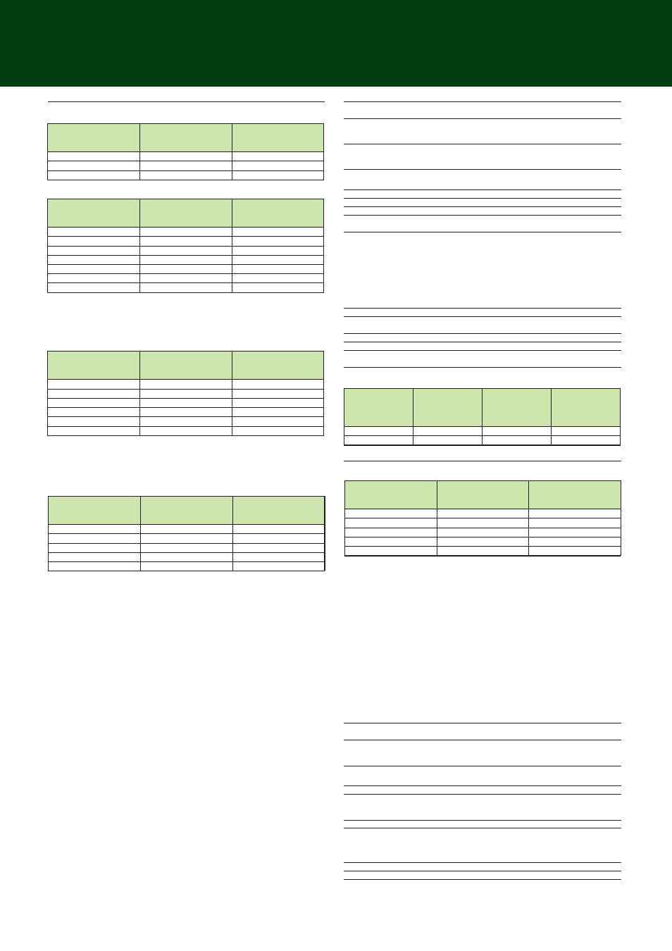
• When the line filter is OFF
Fundamental
Frequency of the
PLL Source
(Hz)
45 to 55
55 to 66
Sample Rate
(S/s)
f
×
900
f
×
750
Window Width against
the FFT Data Length
(Frequency of the
Fundamental Wave)
10
12
Upper Limit of the
Measured Order
50
50
Frequency
45 Hz
Ϲ
f
Ϲ
66 Hz
66 Hz
Ͻ
f
Ϲ
440 Hz
440 Hz
Ͻ
f
Ϲ
1 kHz
1 kHz
Ͻ
f
Ϲ
2.5 kHz
2.5 kHz
Ͻ
f
Ϲ
3.3 kHz
Voltage and Current
±
(reading error + measurement
range error)
0.2% of reading + 0.04% of range
0.5% of reading + 0.05% of range
1% of reading + 0.05% of range
2.5% of reading + 0.05% of range
8% of reading + 0.05% of range
Power
±
(reading error + measurement
range error)
0.4% of reading + 0.05% of range
1.2% of reading + 0.1% of range
2% of reading + 0.1% of range
5% of reading + 0.15% of range
16% of reading + 0.15% of range
• When the line filter (5.5 kHz) is ON
Accuracy
If the fundamental frequency is between 1 kHz and 2.6 kHz
Add 0.5% of reading to the voltage and current accuracy for frequencies greater than 1
kHz.
Add 1% of reading to the power accuracy for frequencies greater than 1 kHz.
If the fundamental frequency is between 1 kHz and 2.6 kHz
Add 0.5% of reading to the voltage and current accuracy for frequencies greater than 1
kHz.
Add 1% of reading to the power accuracy for frequencies greater than 1 kHz.
• If the fundamental frequency is between 400 Hz and 1 kHz
Add 1.5% of reading to the voltage and current accuracy for frequencies greater than 10
kHz.
Add 3% of reading to the power accuracy for frequencies greater than 10 kHz.
• If the fundamental frequency is between 1 kHz and 2.6 kHz
Add 0.5% of reading to the voltage and current accuracy for frequencies greater than 1
kHz and less than or equal to 10 kHz.
Add 7% of reading to the voltage and current accuracy for frequencies greater than 10
kHz.
Add 1% of reading to the power accuracy for frequencies greater than 1 kHz and less than
equal to 10 kHz.
Add 14% of reading to the power accuracy for frequencies greater than 10 kHz.
However, all the items below apply to all tables.
• When the crest factor is set to 3
• When
λ
(power factor) = 1
• Power figures that exceed 440 Hz are reference values.
• For external current sensor range, add 0.2 mV to the current accuracy and add (0.2 mV/
external current sensor range rating)
×
100% of range to the power accuracy.
• For 30A direct current input range, add 0.2 mA to the current accuracy and add (0.2 mA/
direct current input range rating)
×
100% of range to the power accuracy.
• For 2A direct current input range, add 2
µ
A to the current accuracy and add (2
µ
A/direct
current input range rating)
×
100% of range to the power accuracy.
• For n
th
order component input, add {n/(m+1)}/50% of (the n
th
order reading) to the n+m
th
order and n-m
th
order of the voltage and current, and add {n/(m+1)}/25% of (the n
th
order
reading) to the n+m
th
order and n-m
th
order of the power.
• Add (n/500)% of reading to the n
th
component of the voltage and current, and add (n/
250)% of reading to the n
th
component of the power.
• Accuracy when the crest factor is 6: The same as when the range is doubled for crest
factor 3.
• The accuracy guaranteed range by frequency and voltage/current is the same as the
guaranteed range of normal measurement.
Frequency
• PLL synchronization method: 2.5 Hz
Ϲ
f
Ϲ
100 kHz
Measurement range
• External sampling clock method: 0.15 Hz
Ϲ
f
Ϲ
5 kHz
Display update
Depends on the PLL source
• PLL synchronization method: 1 s or more
• External sampling clock method: 20 s or more
PPL Timeout value
Depends on the PLL source
• PLL synchronization method: 5 s or more
• External sampling clock method: 40 s or more
• IEC Harmonic Measurement
Item
Specifications
Measured source
Select an input element or an
Σ
wiring unit
Format
PLL synchronization method
Frequency range
Fundamental frequency of the PLL source is in the range of 45 Hz
to 66 Hz.
PLL source
• Select the voltage or current of each input element (external
current sensor range is greater than or equal to 500 mV) or the
external clock (fundamental frequency).
• Input level
Greater than or equal to 50% of the measurement range rating
when the crest factor is 3
Greater than or equal to 100% of the measurement range rating
when the crest factor is 6
• Be sure to turn the frequency filter ON.
FFT data length
9000
FFT processing word
32 bits
length
Window function
Rectangular
Anti-aliasing filter
Set using a line filter (5.5 kHz).
Interharmonic
Select OFF, Type1, or Type2.
measurement
Sample rate (sampling frequency), window width, and upper limit of measured order
Accuracy
However, all the items below apply.
• When the crest factor is set to 3
• When
λ
(power factor) = 1
• Power figures that exceed 440 Hz are reference values.
• For external current sensor range, add 0.03 mV to the current accuracy and add (0.03 mV/
external current sensor range rating)
×
100% of range to the power accuracy.
• For 30A direct current input range, add (0.1 mA/direct current input range rating)
×
100% of
range to the power accuracy.
• For 2A direct current input range, add (1
µ
A/direct current input range rating)
×
100% of
range to the power accuracy.
• For n
th
order component input, add {n/(m+1)}/50% of (the n
th
order reading) to the n+m
th
order and n-m
th
order of the voltage and current, and add {n/(m+1)}/25% of (the n
th
order
reading) to the n+m
th
order and n-m
th
order of the power (only when applying a single
frequency).
• Accuracy when the crest factor is 6: The same as when the range is doubled for crest
factor 3.
• The accuracy guaranteed range by frequency and voltage/current is the same as the
guaranteed range of normal measurement.
Frequency
45 Hz
Ϲ
f
Ϲ
1 MHz
Measurement range
Display update
Depends on the PLL source
(Approximately 200 ms when the frequency of the PLL source is 45
Hz to 66 Hz.)
• Waveform Computation Function
Item
Specifications
Computed source
Voltage, current, and active power of each input element; torque
(analog input) and speed (analog input) of motor input; and motor
output
Equation
Two equations (MATH1 and MATH2)
Operator
+, –, *, /, ABS (absolute value), SQR (square), SQRT (square root),
LOG (natural logarithm), LOG10 (common logarithm), EXP
(exponent), NEG (negation), AVG2, AVG4, AVG8, AVG16, AVG32,
AVG64 (exponential average).
Sampling clock
Fixed to 200 kHz
Display update
Data update interval + computing time