Meeting your system upgrade needs, Booster (plz2004wb), External controls parallel operation – Atec Kikusui-PLZ-4W Series User Manual
Page 8
8
P L Z - 4 W S E R I E S
Booster (PLZ2004WB)
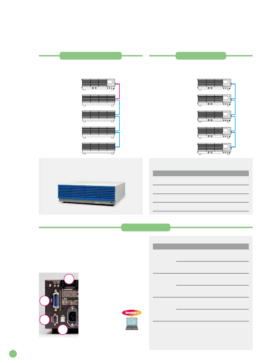
To offer a large capacity at low cost, PLZ2004WB is
available as a booster unit for the PLZ1004W system. Up to
four booster units can
b e c o n n e c t e d i n
p a r a l l e l w i t h o n e
P L Z 1 0 0 4 W u n i t
serving as the master
unit (max. 9 kW, 1800
A). To connect these
units requires the use
of optional cables -
one
PC02-PLZ-4W
parallel cable and as
many
PC01-PLZ-4W
parallel cables as the
number of booster
units to be connected.
External controls
Parallel operation
Without using boosters, you can connect up to five units of
the same model in parallel, including the master unit (max. 5
k W, 1 0 0 0 A ) . I n t h e
p a r a l l e l c o n n e c t i o n
configuration, one control
master operates with
one or more slave units,
enabling you to control
the entire system and
v i e w i t s d a t a o n t h e
master unit’s panel. To
c o n n e c t t h e u n i t s
requires the use of as
many optional parallel
cables (
PC01-PLZ-4W
)
as the number of units to
be connected.
Booster PLZ2004WB
Operating voltage: 1.5 to 150 V Current: 400 A Power: 2000 W Input
power supply voltage range: 100 to 240 VAC (90 to 250 VAC), single-phase
connection Power consumption: Max. 200 VA Weight: Approx. 23 kg
Dimensions: 429.5 (455) mm W
× 128 (150) mm H × 550 (600) mm D
* PLZ2004WB is a dedicated booster for PLZ1004W.
It cannot be used with any other model.
Supported interface standards
• IEEE Std 488.2-1992
• IEEE Std 488.1-1987
• TIA/EIA-232F
• SCPI 1999.0
• USB 2.0 (Full Speed)
• USBTMC 1.0
Measuring instrument driver
You can download the
measuring instrument
driver (freeware) from
our Web site. Please
visit the site and make
full use of it.
(www.kikusui.co.jp)
External
analog
GPIB
RS232C
USB
Meeting Your System Upgrade Needs
Capacity Expansion Functions and External Control Functions
* Large-capacity systems of 9 kW or more, rack-mounted systems, and other types of systems are supported.
For more information, please contact our sales representatives.
Master (PLZ1004W)
Booster (PLZ2004WB)
Booster (PLZ2004WB)
Booster (PLZ2004WB)
Booster (PLZ2004WB)
Parallel cable
PC02-PLZ-4W
Parallel cable
PC01-PLZ-4W
Parallel cable
PC01-PLZ-4W
Parallel cable
PC01-PLZ-4W
(for connecting the master
unit to the booster unit)
Master (PLZ1004W)
Slave (PLZ1004W)
Slave (PLZ1004W)
Slave (PLZ1004W)
Slave (PLZ1004W)
Parallel cable
PC01-PLZ-4W
Parallel cable
PC01-PLZ-4W
Parallel cable
PC01-PLZ-4W
Parallel cable
PC01-PLZ-4W
Number of parallel connected units and capacities
(maximum currents and maximum voltages)
Slave unit
1 unit
2 units
3 units
4 units
PLZ164W/
PLZ164WA
66A
330W
99A
495W
132A
660W
165A
825W
PLZ334W
132A
660W
198A
990W
264A
1320W
330A
1650W
PLZ664WA
264A
1320W
396A
1980W
528A
2640W
660A
3300W
PLZ1004W
400A
2000W
600A
3000W
800A
4000W
1000A
5000W
External controls are provided by means of the inputs from
the GPIB, RS-232C, USB, and analog interfaces. The GPIB,
RS-232C, and USB interfaces comply with the standards
listed below. Using the external analog inputs, you can
p e r fo r m s u c h o p e r a t i o n s a s ex t e r n a l vo l t a g e - o r
resistance-based control, load on/off, current range
switching and input current monitor output.
Voltage- or resistance-based external analog controls
Control method
Operation mode
Explanation
Voltage
CC, CP, CV
A change of 0 to 10 V causes a
change of 0% to 100% of the rated
range value.
CR
A change of 0 to 10 V causes a
change ranging from the maximum
to minimum values of the range.
Resistance
(proportional)
CC, CP, CV
A change of 0
Ω to 10 kΩ causes a
change of 0% to 100% of the rated
range value.
CR
A change of 0
Ω to 10 kΩ causes a
change ranging from the maximum
to minimum values of the range.
Resistance
(inversely
proportional)
CC, CP, CV
A change of 10 k
Ω to 0 Ω causes a
change of 0% to 100% of the rated
range value.
CR
A change of 10 k
Ω to 0 Ω causes a
change ranging from the maximum
to minimum values of the range
Other external analog controls
Load on/off control and monitoring Range control and monitoring in each
current range switching mode Pause clear during trigger input sequences
Forcible alarm generation upon alarm input Input current monitoring by the
current monitor Short signal output from the relay contact
* To connect to the external analog input interface, use a commercially available
MIL-standard 20-pin connector or the accessory kit (OP01-PLZ-4W).