Support for advanced tests, Remote sensing function, Switching function – Atec Kikusui-PLZ-4W Series User Manual
Page 6: Soft start function, Short-circuit function, Load on/off operations, Sequence function, Control functions and operation support functions, Normal sequence, Fast sequence
6
P L Z - 4 W S E R I E S
Remote sensing function
The remote sensing function compensates for voltage drops
in load lines. It is used to set resistance and voltage values
correctly and to make accurate voltage and power
measurements. Particularly, the function improves the
transitional characteristics in constant voltage, constant
power and constant resistance modes, leading to stable
operation. (The maximum voltage that can be compensated
for is 2 V for one way.)
Switching function
In constant current and constant resistance modes,
switching operations can be performed at up to 20 kHz. The
switching setting parameters such as the switching level,
switching frequency, and duty factor can be changed even
while the load is on.
[Setting parameters]
Operation mode: CC and CR
Duty factor: 5% to 95%, in
steps of 0.1%
Frequency setting range: 1 Hz to 20 kHz
Frequency setting
resolution: 0.1 Hz for 1 Hz to 10 Hz; 1 Hz for 10 Hz to 100 Hz; 10 Hz for 100 Hz to 1
kHz; 100 Hz for 1 kHz to 20 kHz
Frequency setting accuracy: ±(0.5% of set)
* The minimum time interval for setting the duty factor is 10
μs.
Soft start function
The soft start function allows the rise time of the current to
be changed in constant current or constant resistance mode
after the output voltage of the device being tested has risen.
Since the rise time for the system can be changed according
to the output-voltage rise time for the device being tested,
you can conduct tests under highly realistic load conditions.
(The soft start time can be selected from the following options - 1, 2, 5, 10, 20, 50,
100, and 200 ms.)
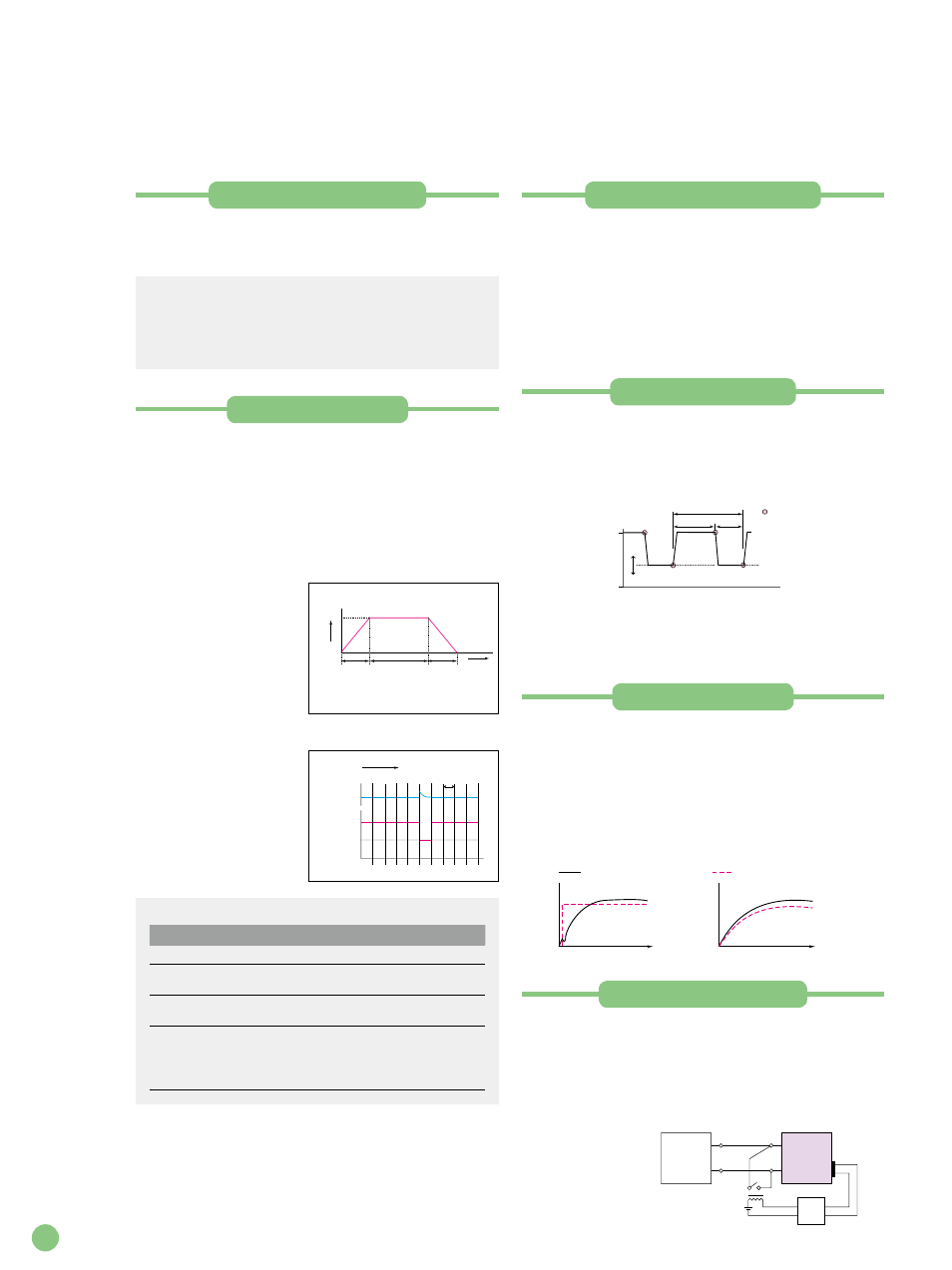
Short-circuit function
When the system is operating in constant current or
constant resistance mode, this function allows you to
instantaneously switch to the maximum current value (in
constant current mode) or to the minimum resistance value
(in constant resistance mode) of the range. Also, since a
contact signal is output to the J1 connector, you can
s h o r t - c i r c u i t t h e
output of the device
under test by driving
the external relay or
other element.
Load on/off operations
In addition to the regular operations, the following types of
load on/off operations are available. You can choose any of
these operations as suitable for your operating environment.
• Start in the load on state
• Display of the elapsed load on time
• Auto load off after the elapse of the set time
• Load on/off control using relay and other external signals
Sequence function
Any sequence patterns can be stored in the built-in memory.
The memory can hold up to 10 normal sequence programs
plus one fast sequence program. Each normal sequence
program can contain a maximum of 256 steps, with the fast
sequence program consisting of up to 1024 steps. You can
edit these programs on the large liquid crystal display (LCD)
monitor.
* Use the sequence creation software tool Wavy (see page XX).
Normal sequence
A different execution time
can be assigned to each
step individually. You can
stop the execution of the
sequence temporar ily
using PAUSE and remove
t h e p a u s e u s i n g a n
external trigger signal.
Fast sequence
Each step is executed at
high speed. The high time
resolution enables high-
speed simulations. The
fast sequence program
can contain up to 1024
steps, which are executed
at even intervals.
7A
Time
100-s ramp
(RAMP ON)
7A
150-s step
(RAMP OFF)
7A
80-s ramp
(RAMP ON)
0.5A
Step 1
Input current
Step 3
Step 2
10A
5A
Execution (RUN)
STEP 1 2 3 4 5 6 7 8 9 10
Trigger output
Input current
TIME BASE
(Execution interval)
Support for Advanced Tests
Control Functions and Operation Support Functions
Sequence setting parameters
Normal sequence
Fast sequence
Operation mode CC, CR, CV, CP
CC, CR
Maximum
number of steps 256
1024
Step execution
time
1 ms to 999 h 59 min
25
μs to 100 ms
Time resolution
1 ms (1 ms to 1 min)
100 ms (1 min to 1 h)
1 s (1 h to 10 h)
10 s (10 h to 100h)
1 min (100 h to 999 h 59 min)
25
μs (25 μs to 100 μs)
100
μs (100 μs to 100 ms)
Rise time for the direct
current power supply
Rise time for the electronic load
Time
When the soft start function is not used
When the soft start function is used
Time
Th
TL
FREQ
0 [A] (0 %)
LEVEL [A] (%)
SET [A] (100 %)
A pulse is output
from the TRIG OUT
terminal at this edge.
Device
under
test
PLZ-4W
Series
+
–
+
–
Large-current relay
Driving
circuit
J1 connector
on the rear
panel