Atec PacificPower-DCR600-20 User Manual
Page 5
DCR600-20
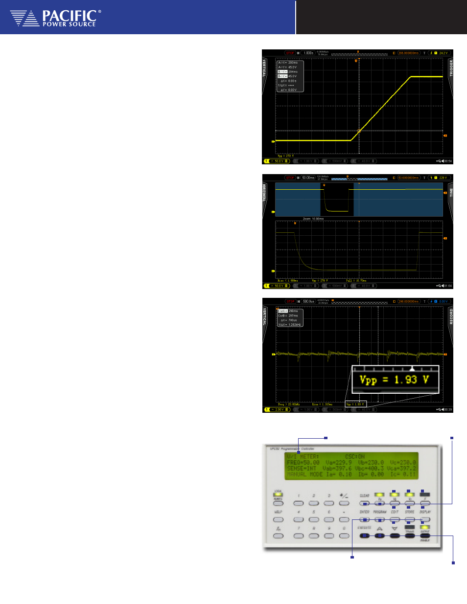
Programmed DC Voltage Dip
This scope screen image shows the result of a programmed
DC voltage drop to 0Vdc for 100 msec under light load condi-
tions. The downward slope is caused by the RC constant of the
DCR600 output capacitance.
Typical Peak to Peak Voltage Ripple
This scope screen image shows a magnified vertical view of the
DC output voltage which illustrates the relatively low Vdc peak
to peak ripple present on the output.
The UPC Controller
part of the AMX Series of Program-
mable AC Power Sources. When used with the DCR unit, AC
voltage amplitudes are scaled to a DC voltage output. The
scaling factor depends on the number of AC output phases
(1 or 3) and the shape of the AC waveform selected.
Indirect Control of DC Power- Simple, Intuitive Operation
For best results, a three phase output and Square waveform is
recommended.
Both the UPC-1 and UPC-32Controllers
are available with
either RS-232 or GPIB remote interface. Commands are
structured in accordance with SCPI (Standard Commands for
Programmable Instruments).
Program Edit and Function Key
Output Control, Slew, and enable Keys
Parameter Control
4 x 16 Character LCD
Display
Using the front panel keyboard and display, all controller
models provide for selection of power source output mode,
coupling, voltage, and frequency.
Programmed DC Voltage Ramp
This scope screen image shows the DV voltage ramping from
0Vdc to 270Vdc using a slew rate of 54Vdc/sec over a 5 second
period.