Atec PacificPower-DCR600-20 User Manual
Page 4
DCR600-20
Principle of Operation
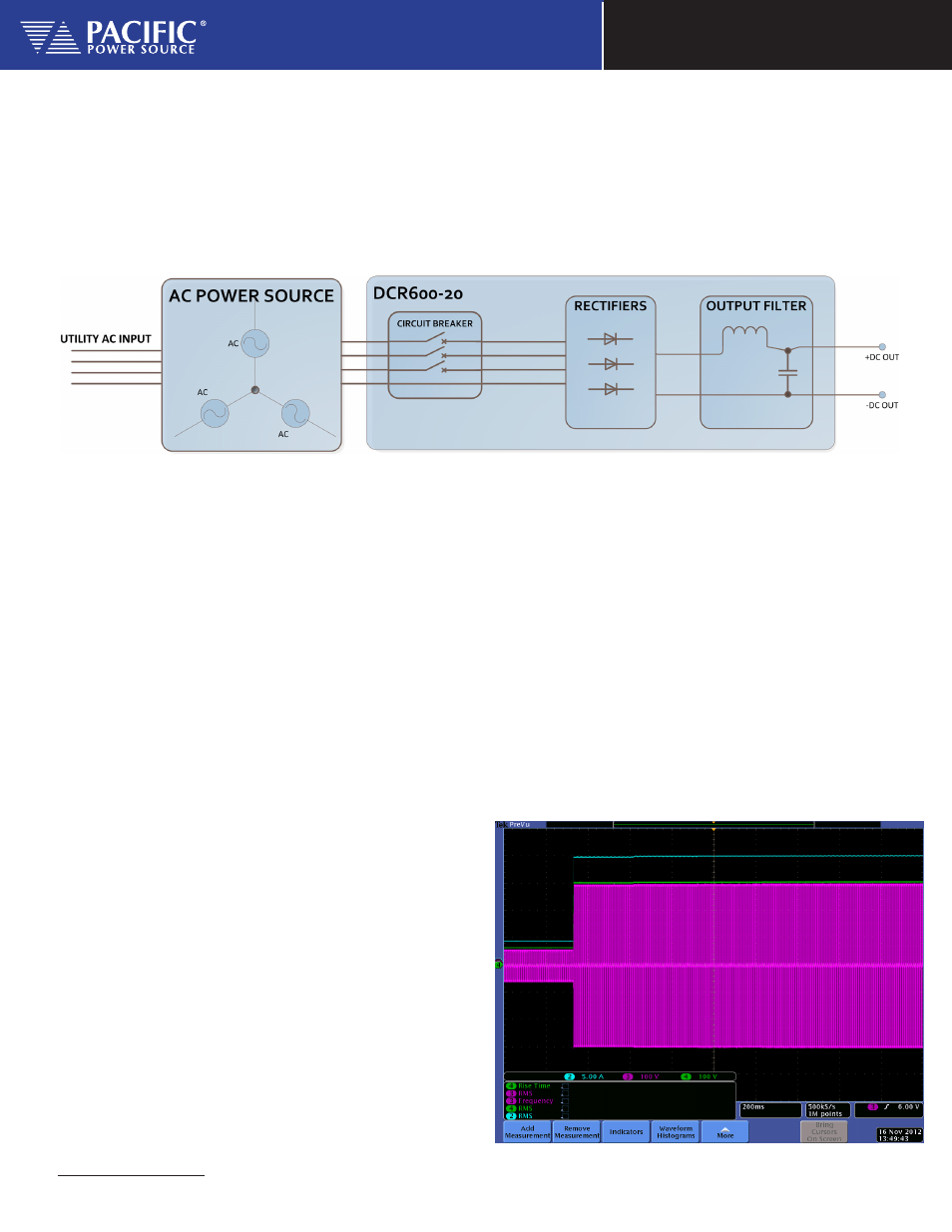
The DCR600-20 uses a three phase diode bridge to rectify the AC input voltage to a single DC rail. By using the square wave
capability of the AMX Series AC Power Sources, low voltage ripple can be accomplished with only minimal bulk DC storage
capacitance at the output. This results in faster DC slew rates compared to a typical 6KW DC Power Supply. No modifications
are needed to the AC Power Source to use the DCR unit as it is fully self-contained. If the DCR unit is placed away from the
AC Power Source used to drive its input, it is recommended to use the external voltage sense capability of the AC Power
Source to minimize line losses
1
.
A block diagram of the DCR unit is shown in the figure below for reference.
Applications
The DCR is most practical for higher Voltage DC applications (100Vdc to 600Vdc) as these ranges are a better fit for the 135V
or 270VAC voltage ranges of the AC power source. Lower voltage settings will generally provide only little DC output power
as the AC Power Source does not deliver higher current at lower voltages. Check the Voltage and Current rating chart of the
AC Power Source model you plan to use to drive the AC input side of the DCR unit.
Applications for DC testing are numerous and only a handful of typical examples are listed here.
• LED Lighting
• Power Conversion, Power Factor Correction
• DC Motors and Actuators
• DC Power Distribution in Avionics
AC Input and DC Output Waveforms
This scope screen image shows three phase square
wave from and the resulting DC Voltage and Current
waveforms into the load.
DC Output Samples
The waveform capture screens shown below represent typical DC output voltages resulting from using the
DCR600-20 with a 345AMX AC Power Source. All data is taken using the recommended AC output parameters
of 400Hz, Square wave and FORM3 AC output mode.
1
Note: No External DC Voltage Sense capability is provided so the distance between the DC load and the DCR unit should be kept to a minimum with sufficiently sized load wire gauge.