Configuration of options – Atec Hioki-8847 User Manual
Page 16
HEAD OFFICE :
81 Koizumi, Ueda, Nagano, 386-1192, Japan
TEL +81-268-28-0562 / FAX +81-268-28-0568
E-mail: [email protected]
HIOKI USA CORPORATION :
6 Corporate Drive, Cranbury, NJ 08512 USA
TEL +1-609-409-9109 / FAX +1-609-409-9108
E-mail: [email protected]
DISTRIBUTED BY
All information correct as of Apr. 27, 2009. All specifi cations are subject to change without notice.
8847E4-94E-00P Printed in Japan
Factory-installed option
*Must specify when ordering
Configuration of options
Note: Options described as ”factory-installed options” must be specified when ordering and cannot be installed by the user. Note: Product names appearing in this catalog are trademarks or registered trademarks of various companies.
PC Software
Voltage measurement
for use with general input modules
CONNECTION CORD 9790
(Thin Type) CAT II 300 V, ultra-
flexible 2.8 mm (0.11 in) diameter test
lead cable, 1.5 m (4.92 ft) length
Note: Attachment clips sold separately.
ALLIGATOR CLIP 9790
-01
Red/black set attaches to the ends
of test leads (
9790)
GRABBER CLIP 9790
-02
Red/black set attaches to the ends
of test leads (
9790)
CONTACT PIN 9790
-03
Red/black set attaches to the ends
of test leads (
9790)
CONNECTION CORD 9197
For high voltage (up to 500 V), 1.8 m
(5.91 ft) length
CONNECTION CORD 9198
For low voltage (up to 300 V), 1.7 m
(5.58 ft) length
10:1 PROBE 9665
Max. rated voltage to earth is same as
for input module, max. input voltage 1
kV rms (up to 500 kHz), 1.5 m (4.92 ft)
length
100:1 PROBE 9666
Max. rated voltage to earth is same as
for input module, max. input voltage 5
kV peak (up to 1MHz), 1.5 m (4.92 ft)
length
Recommended
Tip Expanders
Attachment clips are sold separately
from CONNECTION CORD 9790.
Purchase the appropriate attachment
clips for your application separately
Tip Expanders
9790
-01
Tip Expanders
9790
-03
Tip Expanders
9790
-02
High-Voltage measurement
for use with power supply
DIFFERENTIAL PROBE 9322
For up to 2 kV DC or 1 kV AC. Use
with either AC Adapter
9418-15
AC ADAPTER 9418-15
For powering Differential probe
9322, 100 to 240 V AC
Not CE marked
WAVE PROCESSOR 9335
Data conversion, print functions, waveform
display, compatible with Windows 95/98/Me,
Windows NT 4.0/2000/XP, and Windows
Vista 32-bit type.
Removable storage (CF card)
Supplied with PC
Card adapter
PC CARD 256M 9727
(256 MB capacity)
PC CARD 512M 9728
(512 MB capacity)
PC CARD 1G 9729
(1 GB capacity)
PC Card Precaution
Use only PC Cards sold by HIOKI.
Compatibility and performance
are not guaranteed for PC cards
made by other manufacturers. You
may be unable to read from or save
data to such cards.
3269
3273-50
3276
3274
3275
CLAMP ON PROBE 3276
DC to 100MHz wideband response,
mA-class current up to 30A rms
CLAMP ON PROBE 3275
DC to 2MHz wideband response,
mA-class current up to 500A rms
CLAMP ON PROBE 3274
DC to 10MHz wideband response,
mA-class current up to 150A rms
CLAMP ON PROBE 3273
-50
DC to 50MHz wideband response,
mA-class current up to 30A rms
POWER SUPPLY 3272
Connect and power up to one CLAMP
ON PROBE to use in combination with
voltage input modules
POWER SUPPLY 3269
Connect and power up to four CLAMP
ON PROBEs to use in combination
with voltage input modules
3272
Current measurement
*Connect directly to the analog input module
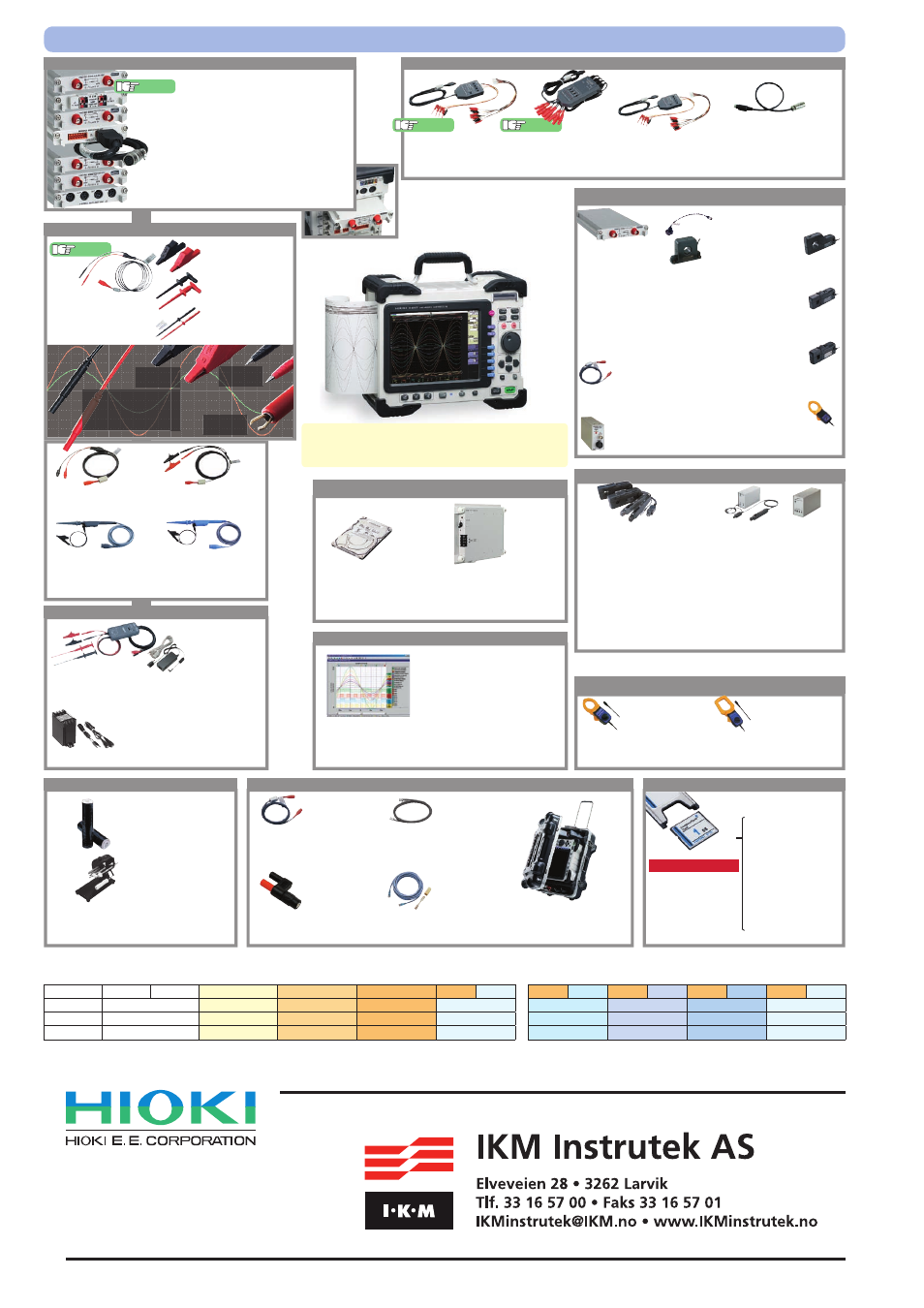
MEMORY HiCORDER 8847
*
The MEMORY HiCORDER
8847 cannot operate alone. You must
install one or more optional input modules in the unit.
Printer options
Logic signal measurement
LOGIC PROBE 9320
-01
4-channel type, for voltage/contact signal
ON/OFF detection (response time 0.5
μsec, miniature terminal type)
LOGIC PROBE 9321
-01
4 isolated channels, ON/OFF
detection of AC/DC voltage
(miniature terminal type)
LOGIC PROBE 9327
4-channel type, for voltage/contact signal
ON/OFF detection (response time 0.1
μsec or higher, miniature terminal type)
CONVERSION CABLE 9323
Used for connecting the
9320/9321
to the
8847 MEMORY HiCORDERs,
because the terminal shapes are different.
* This cable is not required for the small-
terminal types
9327, 9320-01, and
9321-01.
Recommended
Recommended
Install by inserting into the main unit. Can be replaced by user.
ANALOG UNIT 8966
TEMP UNIT 8967
HIGH RESOLUTION UNIT 8968
STRAIN UNIT 8969
...CONVERSION CABLE
9769, Two cables included
FREQ UNIT 8970
............(available middle 2009)
CURRENT UNIT 8971
............(available middle 2009)
DC/RMS UNIT 8972
LOGIC UNIT 8973
Recommended
Input modules
Input cables are not supplied. Please purchase the appropriate cable for the intended application.
DC POWER UNIT 9784
Factory-installed option - not user
installable, built in on the bottom
case. 10 to 28 V DC drive.
HD UNIT 9664
Factory-installed option. 80GB
Other options
CARRYING CASE 9783
Hard trunk type, also suitable for
shipping/transporting the 8847
RECORDING PAPER 9231
A4 width 216 mm (8.50 in) × 30
m (98.43 ft), 6 rolls/set
PAPER WINDER 220H
Paper width 70 to 220 mm (2.76
to 8.66 inch), 100V AC Only
Not CE marked
LAN CABLE 9642
Straight Ethernet cable, supplied with straight to
cross conversion cable, 5 m (16.41 ft) length
CONNECTION CORD 9217
Cord has insulated BNC connectors at both ends,
and connects to insulated BNC connectors on
input module. 1.7 m (5.58 ft) length
CONNECTION CORD 9165
Cord has metallic BNC connectors at
both ends, and connects to metallic BNC
connectors. 1.5 m (4.92 ft) length
CONVERSION ADAPTER 9199
Banana-to-BNC, use to connect to BNC
terminal on Input Module
Not CE marked
■
Combination example:
8847
(with mix of logic modules and standard analog modules) * 16 logic input channels installed as standard in unit, separate logic probes required
8847 × 1
Memory 64 MW
Logic 32 ch
Logic 48 ch
Logic 64 ch
Logic 64 ch Analog 2 ch
Logic 64 ch Analog 4 ch Logic 64 ch Analog 6 ch Logic 64 ch Analog 8 ch Logic 64 ch Analog 10 ch
Logic input unit
8973 Ч 1
8973 Ч 2
8973 Ч 3
8973 Ч 3
8973 Ч 3
8973 Ч 3
8973 Ч 3
8973 Ч 3
Analog input unit
—
—
—
8966 Ч 1
8966 Ч 2
8966 Ч 3
8966 Ч 4
8966 Ч 5
Input cable
—
—
—
9198 Ч 2
9198 Ч 4
9198 Ч 6
9198 Ч 8
9198 Ч 10
PT 9303
Insulation transformer, 400V or 200V AC input,
10V AC output, for AC power line measurement.
Required along with the Conversion Adapter 9199.
SENSOR UNIT 9555
-10
Power supply unit for the 9272 to
the 9279 clamp sensors, except
for connecting to the Current unit
8971, for signal output 9217 is
necessary.
CURRENT UNIT 8971
CLAMP ON SENSOR
9272
-10
Enables observation of AC current
waveforms. Input: 1 to 100kHz, selectable
20 and 200A rms ranges, 2V AC output
CONVERSION CABLE 9318
To connect the
9272 to 9279 and the 8971
CLAMP ON PROBE
9018
-50
Enables observation of AC
current waveforms. 40 Hz to 3 kHz
response, input 10 A to 500 A range,
output 0.2 V AC/range
CLAMP ON PROBE
9132
-50
Enables observation of AC
current waveforms. 40 Hz to 1 kHz
response, input 20 A to 1000 A range,
output 0.2 V AC/range
Current measurement
* Use for commercial power line, 50/60 Hz
(Useless the power supply)
Current measurement
* To connect the clamp-on sensor via the conversion cable, Band
width DC to 100 kHz class
UNIVERSAL CLAMP ON
CT 9277
Observe waveforms from DC to distorted
AC. DC to 100kHz response, input 20A /
output 2V AC
UNIVERSAL CLAMP ON
CT 9278
Observe waveforms from DC to distorted
AC. DC to 100kHz response, input 200A /
output 2V AC
UNIVERSAL CLAMP ON
CT 9279
Observe waveforms from DC to distorted
AC. DC to 20kHz response, input 500A /
output 2V AC, Not CE marked
AC/DC CURRENT
SENSOR 9709
Pass through & high precision type, Observe
waveforms from DC to distorted AC. DC to
100kHz response, input 500A / output 2V AC
CONNECTION CORD 9217
Cord has insulated BNC connectors
at both ends, and connects to the
9555-10 and input module.