Data analysis on the computer, Options specifications (sold separately), Logic probe 9320 – Atec Hioki-8847 User Manual
Page 15: Logic probe 9321, Differential probe 9322, Dc power unit 9784, Right side, Wave processor 9335, Features
15
■
Options specifications (sold separately)
LOGIC PROBE 9320
-01
/9327
(Accuracy at 23
±5 °C/73 ±
9 °F, 35 to 80 % rh ; accuracy/product
guaranteed for 1 year)
Function
Detection of voltage signal or relay contact signal for High/Low state recording
Input
4 channels
(common ground between unit and channels)
,
Digital/contact input switchable
(contact input can detect open-collector signals)
,
Input impedance: 1 MΩ
(with digital input, 0 to +5 V)
, 500 kΩ or more
(with
digital input, +5 to +50 V)
, pull-up resistance: 2 kΩ
(contact input: internally
pulled up to +5 V)
Digital input threshold 1.4 V/2.5 V/4.0 V
Contact input
detection resistance
1.5 kΩ or higher
(open)
and 500 Ω or lower
(short)
, 3.5 kΩ or higher
(open)
and 1.5 kΩ or lower
(short)
, 25 kΩ or higher
(open)
and 8 kΩ or lower
(short)
Response speed 9320
-01
: 500 ns or lower,
9327: detectable pulse width 100 ns or higher
Max. allowable input 0 to +50 V DC
(the maximum voltage that can be applied across input pins without damage)
Cable length and mass: Main unit cable 1.5 m (4.92 ft), input section cable 30 cm (0.98 ft),
approx. 150 g (5.3 oz)
Note: The unit-side plug of the
9320-01 and 9327 is different from the 9320.
LOGIC PROBE 9321
-01
(Accuracy at 23
±5 °C/73 ±
9 °F, 35 to 80 % rh ; accuracy/product
guaranteed for 1 year)
Function
Detection of AC or DC relay drive signal for High/Low state recording
Can also be used for power line interruption detection
Input
4 channels
(isolated between unit and channels)
, HIGH/LOW range switching
Input impedance: 100 kΩ or higher
(HIGH range)
, 30 kΩ or higher
(LOW
range)
Output (H) detection 170 to 250 V AC, ±DC (70 to 250 V )
(HIGH range)
60 to 150 V AC, ±DC (20 to 150 V)
(LOW range)
Output (L) detection 0 to 30 V AC, ±DC (0 to 43 V)
(HIGH range)
0 to 10 V AC, ±DC (0 to 15 V)
(LOW range)
Response time
Rising edge 1ms max., falling edge 3ms max.
(with HIGH range at
200 V DC, LOW range at 100 V DC)
Max. allowable input 250 Vrms
(HIGH range)
, 150 Vrms
(LOW range) (the maximum voltage
that can be applied across input pins without damage)
Cable length and mass: Main unit cable 1.5 m (4.92 ft), input section cable 1 m (3.28 ft), approx.
320 g (11.3 oz)
Note: The unit-side plug of the
9321-01 is different from the 9321.
Cable length and mass: Main unit cable 1.3 m (4.27 ft), input section cable 46 cm (1.51 ft),
approx. 350 g (12.3 oz)
DIFFERENTIAL PROBE 9322
(Accuracy at 23
±5 °C/73 ±9 °F, 35 to 80 % rh after 30 minutes of
warm-up time, accuracy/product guaranteed for 1 year)
Function
For high-voltage floating measurement, power line surge noise
detection, RMS rectified output measurement
DC mode
For waveform monitor output,
Frequency characteristics: DC to 10 MHz
(±3 dB)
,
Amplitude accuracy: ±1 % of full scale
(at max. 1000 V DC)
, ±3% of full
scale
(at max. 2000 V DC) (full scale: 2000 V DC)
AC mode
For detection of power line surge noise, frequency characteristics: 1 kHz to 10 MHz
±3 dB
RMS mode
DC/AC voltage RMS output detection,
Frequency characteristics: DC, 40 Hz to 100 kHz,
Response speed: 200 ms or less
(400 V AC)
, accuracy: ±1 % of full scale
(DC, 40 Hz to 1 kHz)
, ±4 % of full scale
(1 kHz to 100 kHz) (full scale: 1000 V AC)
Input
Input type: balanced differential input,
Input impedance/capacitance: H-L 9 MΩ/10 pF, H/L-unit 4.5 MΩ/20 pF,
Max. rated voltage to earth: when using grabber clip 1500V AC/DC
(CAT II)
,
600 V AC/DC
(CAT III)
, when using alligator clip: 1000 V AC/DC
(CAT II)
,
600 V AC/DC
(CAT III)
Max. allowable input 2000 V DC, 1000 V AC
(CAT II)
, 600 V AC/DC
(CAT III)
Output
Voltage divider for 1/1000 of input,
BNC connectors
(output switchable for 3 modes DC, AC, RMS)
Power source
(1) Connect the AC ADAPTER 9418-15, (2) Connect to HiCORDER
logic terminal via the POWER CORD 9324 and CONVERSION
CABLE 9323
Dimensions and mass: approx. 290 (11.42in) W × 29 (1.14in) H × 219.5 (8.64in) D mm,
approx. 1.2 kg (42.3 oz)
Accessories: None
DC POWER UNIT 9784
Rated input voltage 10 to 28 V DC
Power requirements 200 VA
(printer used)
Note: Factory-installed option, build in on the rear of the main unit
DC power supply module
integrated on rear panel
Right side
External control
terminals
Standard logic
inputs
Input modules can be
freely interchanged
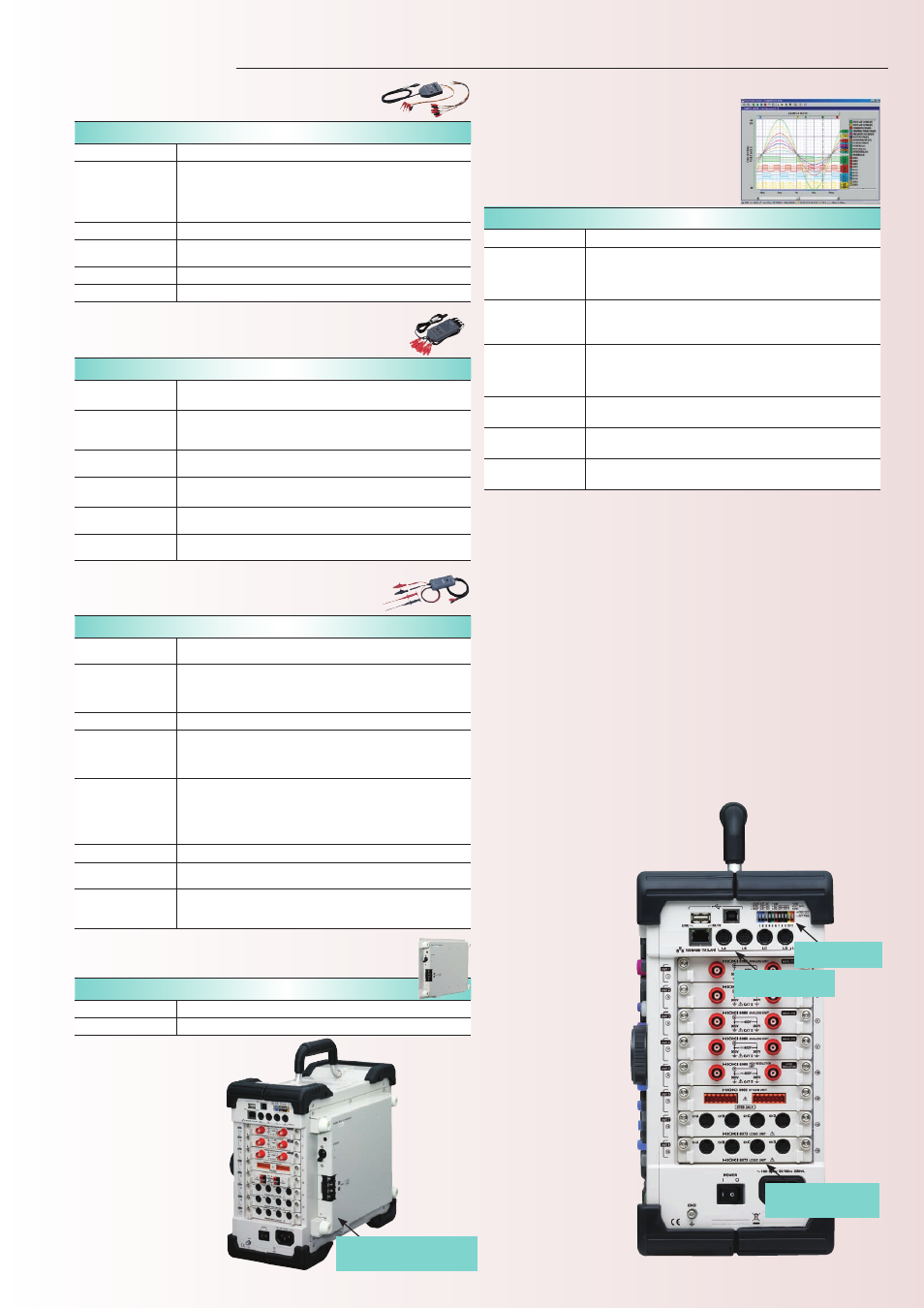
WAVE PROCESSOR 9335
Distribution media
One CD-R
Operating
environment
Computer equipped with Pentium (133 MHz) or better CPU and at least
32 MB of memory, and running under Windows 95/98/Me, Windows
NT 4.0/2000/XP, or Windows Vista 32-bit type
(recommended system:
Pentium (200 MHz) or better with at least 64 MB of memory)
Display functions
Waveform display/X-Y display/digital value display/cursor function/
scroll function/maximum number of channels (32 channels analog, 32
channels logic)/gauge display (time, voltage axes)/graphical display
File loading
Readable data formats (.MEM, .REC, .RMS, .POW)
Maximum loadable file size: Maximum file size that can be saved by
a given device (file size may be limited depending on the computer
configuration)
Data conversion
Conversion to CSV format, tab delimited, space delimited/data culling
(simple)/convert for specified channel/batch conversion of multiple files
Print functions
Print formatting (1 up, 2-to-16 up, 2-to-16 rows, X-Y 1-to-4 up) /preview/
hard copy functions usable on any printer supported by operating system
Other
Parameter calculation/search/clipboard copy/launching of other
applications
Data analysis on the computer
■
Features
Waveform display, data calculation, printing function