Inputs and outputs – Atec Anritsu-68369ANV User Manual
Page 20
18
INPUTS AND OUTPUTS
AM IN:
Accepts an external signal to amplitude modulate the RF
output signal. Front or rear-panel input, 50
Ω or 600Ω impedance,
both selectable from front-panel modulation menu.
FM IN:
Accepts an external signal to frequency modulate the RF
output signal. Front or rear-panel input, 50
Ω or 600Ω impedance,
both selectable from front-panel modulation menu.
IN:
Accepts an external TTL compatible signal to pulse modu-
late the RF output signal. Front or rear-panel input, selectable
from front-panel modulation menu.
PULSE TRIG IN:
Accepts an external TTL compatible signal to
pulse modulate the RF output signal or trigger or gate the internal
pulse generator. Front or rear-panel input, selectable from front-
panel modulation menu.
EXT ALC IN (External ALC Input):
Provides for leveling the
RF output signal externally with either a detector or power meter.
RF OUTPUT:
Provides for RF output from 50
Ω impedance source.
K or V Connector, female. Option 9 moves the RF Output
connector to the rear panel.
10 MHz REF IN:
Accepts an external 10 MHz ±100 Hz, 0 to
+10 dBm time-base signal. Automatically disconnects the internal
high-stability time-base option, if installed. 50
Ω impedance.
10 MHz REF OUT:
Provides a 0.5V p-p, AC coupled,
10 MHz signal derived from the internal frequency standard.
50
Ω impedance.
HORIZ OUT (Horizontal Sweep Output):
Provides 0V at the
beginning and + 10V at end of sweep, regardless of sweep width.
In CW mode, the voltage is proportional to frequency between
0V at low end and +10V at the high end of range. In CW mode, if
CW RAMP is enabled, a repetitive 0V to +10V ramp is provided.
AM OUT:
Provides video modulating signal from internal
AM generator.
FM OUT:
Provides video modulating signal from internal
FM generator.
PULSE VIDEO OUT:
Provides video modulating signal from
internal pulse generator or external pulse input.
PULSE SYNC OUT:
Provides a TTL compatible signal
synchronized to the internal pulse modulation output.
AUX I/O (Auxiliary Input/Output):
Provides for most of the front
and rear panel BNC connections through a single, 25-pin, D-type
connector. Supports master-slave operation with another 68XXXC
or 69XXXB synthesizer or allows for a single-cable interface with
the Model 56100A Scalar Network Analyzer and other ANRITSU
instruments. Provides V/GHz and Sequential Sync Connection.
SERIAL I/O (Serial Input/Output):
Provides access to RS-232
terminal ports to support service and calibration functions, and
master/slave operation.
IEEE-488 GPIB:
Provides input/output connections for the General
Purpose Interface Bus (GPIB).
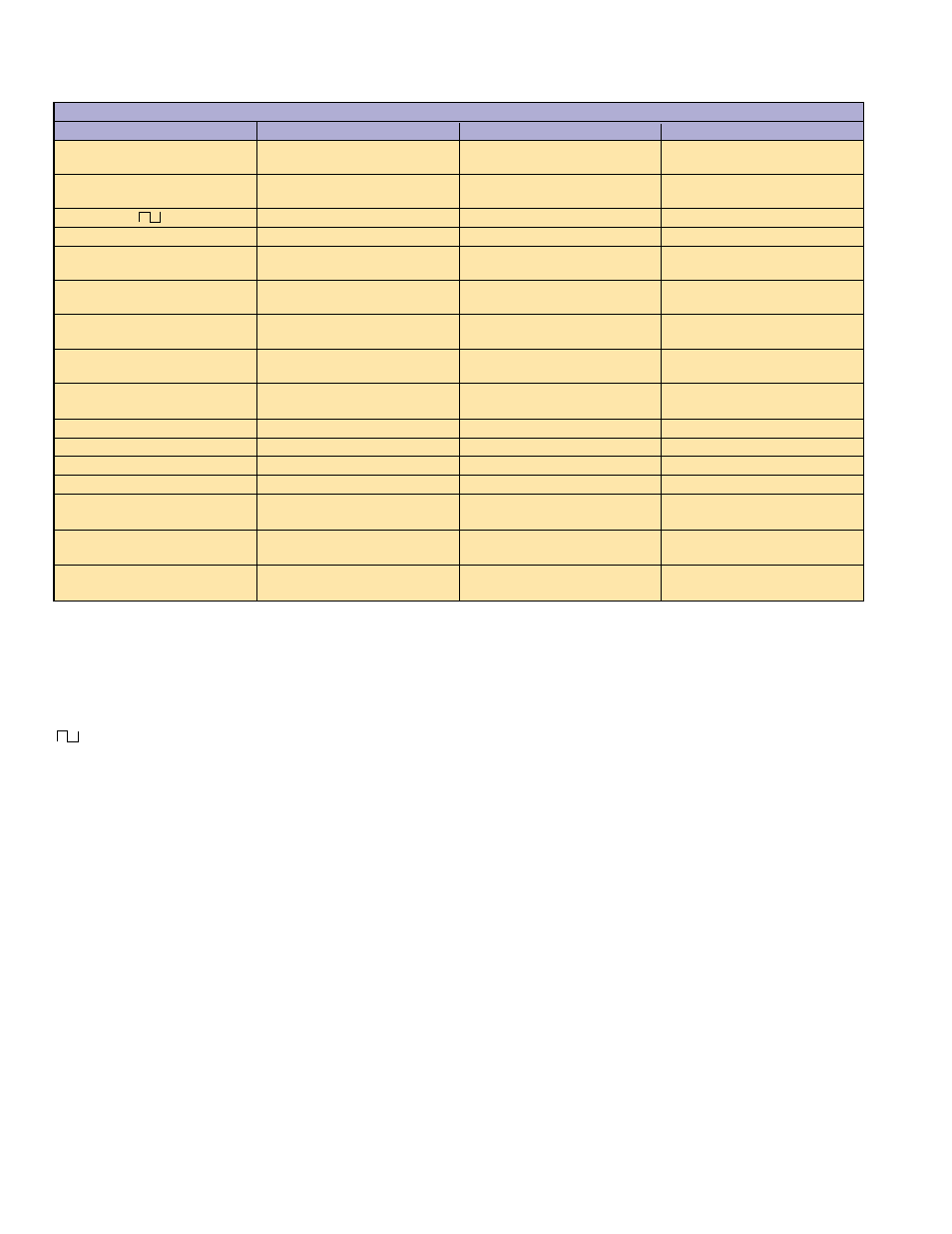
Input/Output Connectors
Nomenclature
Type
Location
Applicable Models
AM IN
BNC
Front and Rear Pane
68100C and 68300C
69100B and 69300B
FM IN
BNC
Front and Rear Panel
68100C and 68300C
69100B and 69300B
IN
BNC
Front and Rear Panel
68100C and 69100B
PULSE TRIG IN
BNC
Front and Rear Panel
68300C and 69300B
EXT ALC IN
BNC
Front and Rear Panel
68000C, 68100C and 68300C
69000B, 69100B and 69300B
RF OUTPUT
K-Connector
V-Connector
Standard-Front Pane
Option 9-Rear Panel
68000C, 68100C and 68300C
69000B, 69100B and 69300B
10 MHz REF IN
BNC
Rear Panel
68000C, 68100C and 68300C
69000B, 69100B and 69300B
10 MHz REF OUT
BNC
Rear Panel
68000C, 68100C and 68300C
69000B, 69100B and 69300B
HORIZ OUT
BNC
Rear Panel
68000C, 68100C and 68300C
69000B, 69100B and 69300B
AM OUT
BNC
Rear Panel
68300C and 69300B
FM OUT
BNC
Rear Panel
68300C and 69300B
PULSE VIDEO OUT
BNC
Rear Panel
68300C and 69300B
PULSE SYNC OUT
BNC
Rear Panel
68300C and 69300B
AUX I/O
25-pin D-type
Rear Panel
68000C, 68100C and 68300C
69000B, 69100B and 69300B
SERIAL I/O
RJ45
Rear Panel
68000C, 68100C and 68300C
69000B, 69100B and 69300B
IEEE-488 GPIB
Type 57
Rear Panel
68000C, 68100C and 68300C
69000B, 69100B and 69300B