E-series cw power sensor specifications, Power linearity general, Continued) – Atec Agilent-E4418B-E4419B User Manual
Page 11: Dimensions
E-Series CW power sensor specifications
(continued)
11
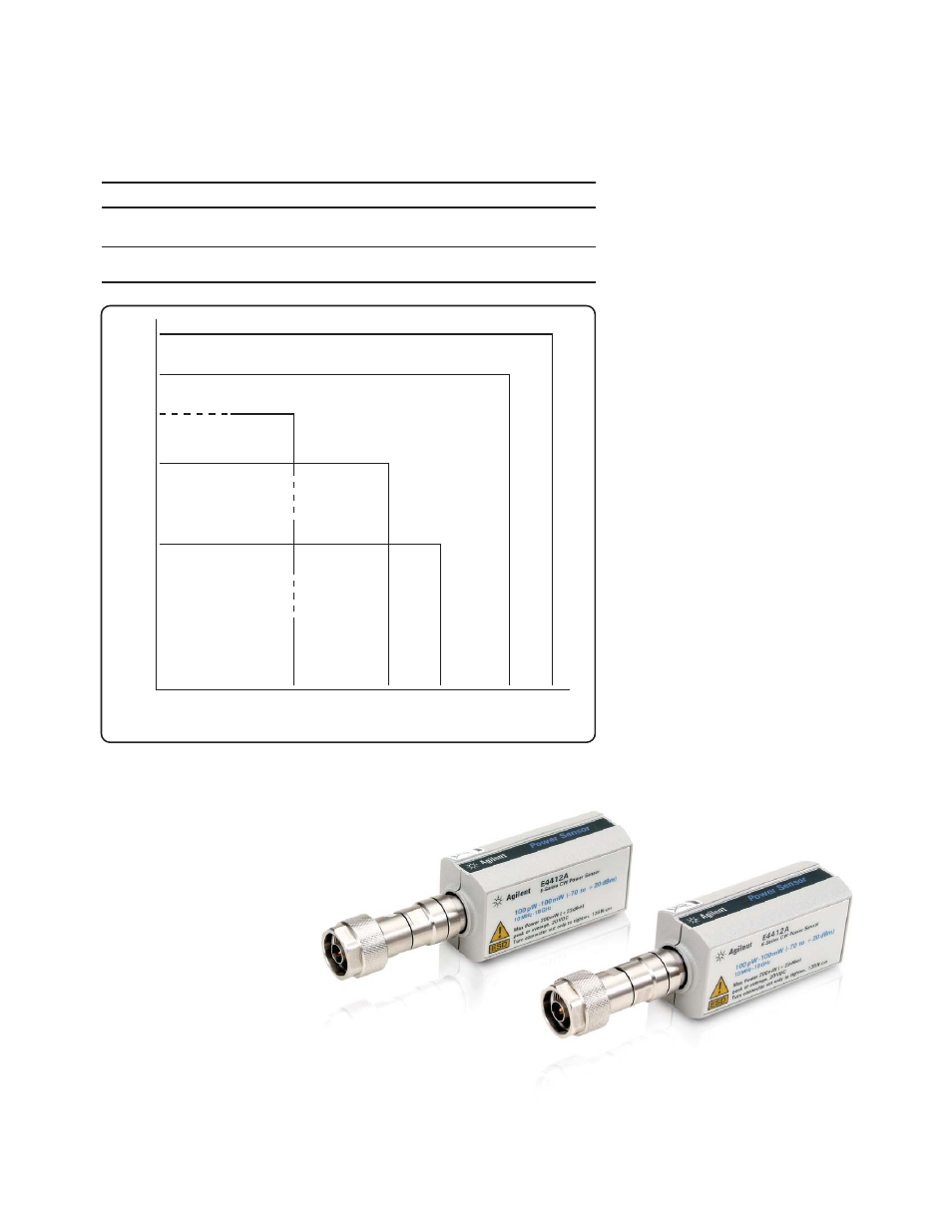
Power linearity
General
Table 6
Power
Temperature (25 °C ±5 °C)
Temperature (0 °C to 55 °C)
±3%
±4.5%
–70 –35 –20 –10 +10 +20
±4%
+3%
A
B
100 pW to 10 mW
(–70 dBm to +10 dBm)
10 mW to 100 mW
(+10 dBm to +20 dBm)
Power Level Used as Reference (dBm)
Figure 1. Relative mode power measurement linearity with EPM Series power meter/E-Series CW power
sensor at 25 °C ± 5 °C (typical)
The chart in Figure 1 shows the typical
uncertainty in making a relative power
measurement, using the same power
meter channel and the same power
sensor to obtain the reference and the
measured values. Example A illustrates
a relative gain (amplifier measurement).
Example B illustrates a relative loss
(insertion loss measurement). This chart
assumes negligible change in frequency
and mismatch occur when transitioning
from the power level used as the
reference to the power level being
measured.
Example A:
P = 10(P)/10 x 1 mW
P = 10 6/10 x 1 mW
P = 3.98 mW
3% x 3.98 mW = 119.4 μW
Example B:
P = 10 (P)/10 x1 mW
P = 10 -35/10 x 1 mW
P = 316 nW
3% x 316 nW = 9.48 nW
where P = power in Watts,
and (P) = power in dBm
Dimensions:
E4412A:
130 mm L x 38 mm W x 30 mm H
E4413A:
102 mm L x 38 mm W x 30 mm H
Weight: 0.18 kg (0.4 lb).
+20
+10
+6
–20
–35
–70
Power Level Being Measured (dBm)
±7%
±10%