Infiniimax 1130 series performance characteristics – Atec Agilent-54855A User Manual
Page 15
15
www.agilent.com/find/infiniimax
InfiniiMax 1130 Series Performance Characteristics
1134A, 1132A, 1131A
Bandwidth*
1134A: > 7 GHz
1132A: > 5 GHz
1131A: > 3.5 GHz
Rise and fall time (10% to 90%)
1134A: < 61 ps
(calculated from tr = 0.43/bandwidth)
1132A: < 86 ps
1131A: < 123 ps
System bandwidth (–3 dB)
1134A with 54855A: 6 GHz
1132A with 54854A: 4 GHz
1131A with 54853A: 2.5 GHz
1131A with 54846B: 2.25 GHz
Input capacitance
1
Cm = 0.10 pF
Cm is between tips
Cg = 0.34 pF
Cg is to ground for each tip
Cdiff = 0.27 pF
Differential mode capacitance = Cm + Cg/2
Cse = 0.44 pF
Single-ended mode capacitance = Cm + Cg
Input resistance*
Differential mode resistance = 50 k
Ω
± 1%
Single-ended mode resistance = 25 k
Ω
± 1%
Input dynamic range
± 2.5 V
Input common mode range
± 6.75 V dc to 100 Hz; ± 1.25 V > 100 Hz
Maximum signal slew rate
18 V/ns when probing a single-ended signal
30 V/ns When probing a differential signal
DC attenuation
10:1 ± 3% before calibration on oscilloscope
10:1 ± 1% after calibration on oscilloscope*
Zero offset error referred to input
< 30 mV before calibration on oscilloscope
< 5 mV after calibration on oscilloscope*
Offset range*
± 12.0 V when probing single-ended
Offset accuracy
< 3% of setting before calibration on oscilloscope
< 1% of setting after calibration on oscilloscope*
Noise referred to input
3.0 mV rms
Propagation delay
~6 ns (this delay can be deskewed relative to other signals)
Maximum input voltage*
40 V peak, CAT I
ESD tolerance
> 8 kV from 100 pF, 300
Ω
HBM
* Denotes warranted specifications, all other are typical.
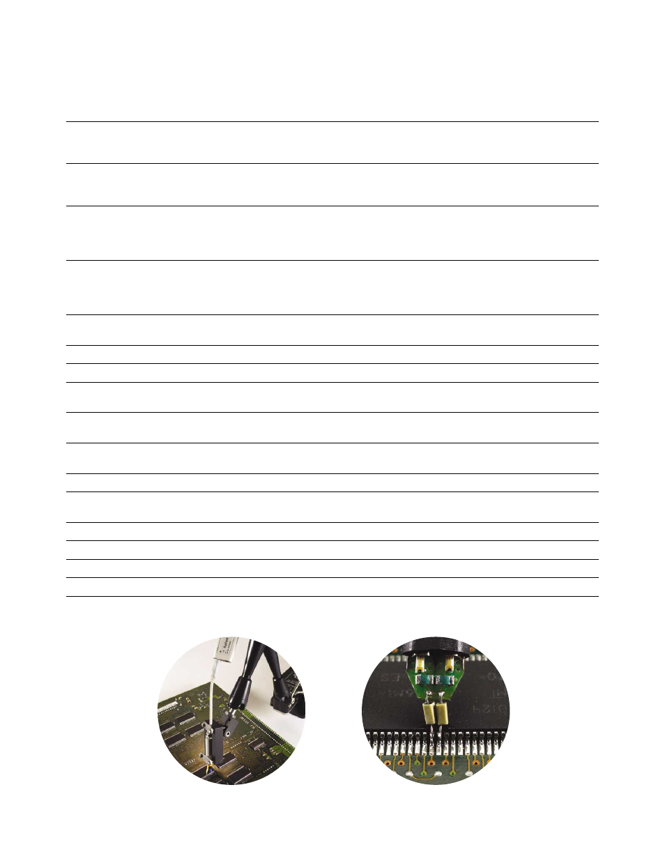
1 Measured using the probe amplifier and solder-in differential probe head with full bandwidth resistors.