Atec Agilent-E4980A-AL User Manual
Page 35
35
DC bias test signal current (1.5 V/2.0 V):
Output current: Max. 20 mA
Option 001 (Power and DC Bias enhance):
DC bias voltage: DC bias voltage applied to DUT is given as:
Equation 18.
Vdut = Vb – 100 × Ib
Vdut [V] DC bias voltage
Vb [V]
DC bias setting voltage
Ib [A]
DC bias current
DC bias current: DC bias current applied to DUT is given as:
Equation 19.
Idut = Vb/(100 + Rdc)
Idut [A] DC bias current
Vb [V]
DC bias setting current
Rdc [Ω] DUT’s DC resistance
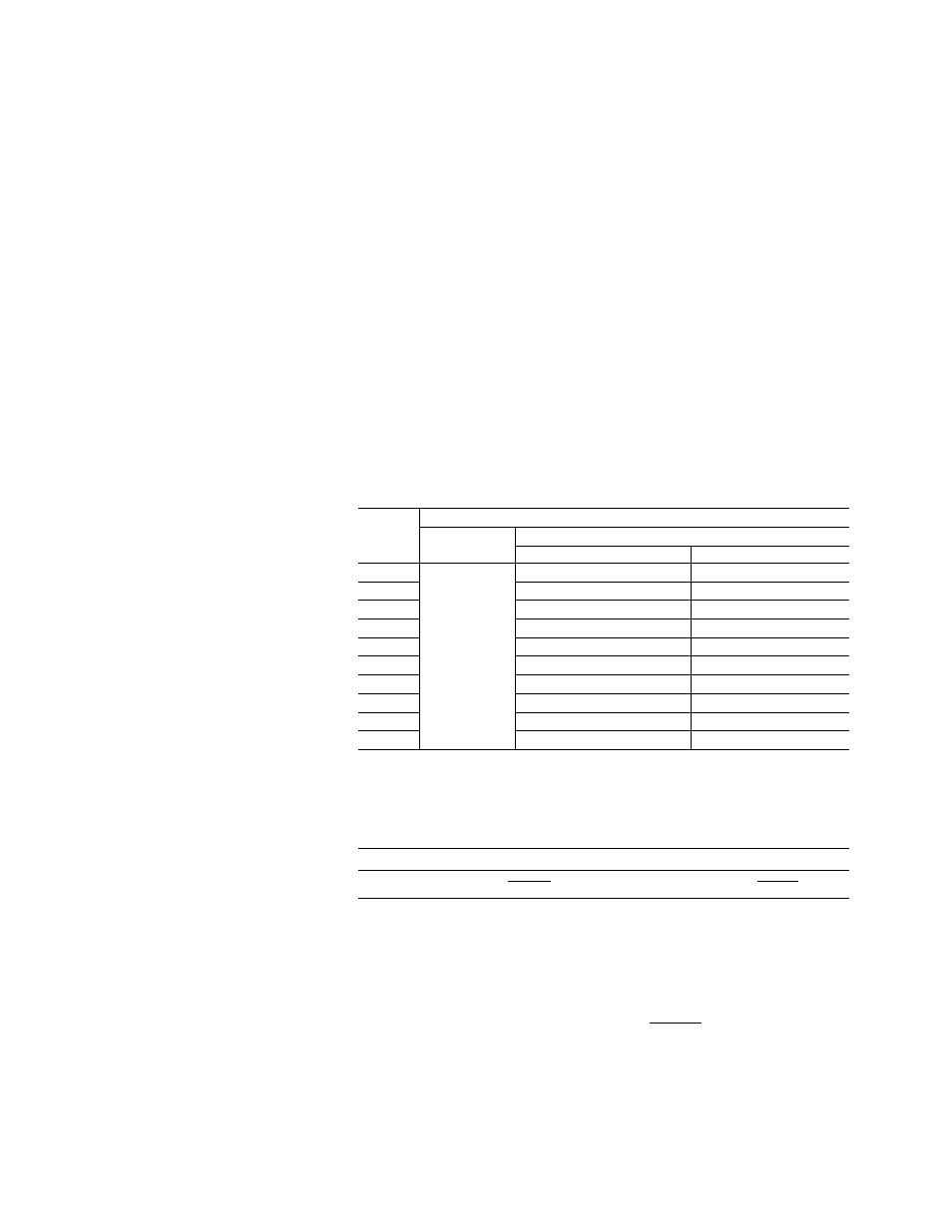
Maximum DC bias current
Table 64. Maximum DC bias current when the normal measurement
can be performed.
Bias current isolation
Impedance
OFF
range [Ω]
ON
Test signal voltage ≤ 2 Vrms
Test signal voltage > 2 Vrms
0.1
20 mA
100 mA
1
20 mA
100 mA
10
20 mA
100 mA
100
20 mA
100 mA
300
2 mA
100 mA
1 k
2 mA
20 mA
3 k
200 µA
20 mA
10 k
200 µA
2 mA
30 k
20 µA
2 mA
100 k
20 µA
200 µA
When DC bias is applied to DUT
When DC bias is applied to the DUT, add the following value to the absolute accuracy Ab.
Table 65. Only when Fm < 10 kHz and |Vdc| > 5 V
SHORT MED,
LONG
0.05% × (100 mV/Vs) × (1 + √(100/Fm))
0.01% × (100 mV/Vs) × (1 + √(100/Fm))
Fm [Hz]
Test frequency
Vs [V]
Test signal voltage
Relative measurement accuracy with bias current isolation
When DC bias Isolation is set to ON, add the following value to the open offset Yo.
Equation 20.
Yo_DCI1 × (1 + 1/(Vs)) × (1 + √(500/Fm)) + Yo_DCI2
Zm [Ω]
Impedance of DUT
Fm [Hz]
Test frequency
Vs [V]
Test signal voltage
Yo_DCI1,2 [S] Calculate this by using Table 61 and 62
Idc [A]
DC bias isolation current
Auto range
mode: 100 mA
Hold range mode:
its values for
the range.