2 enclosure grounding: ground-mount – Alpha Technologies LPE Enclosure User Manual
Page 15
031-302-B0-001 Rev A
15
2.0
Installation, continued
2.3
Enclosure Installation, Ground-mount, continued
2.3.2 Enclosure Grounding: Ground-mount
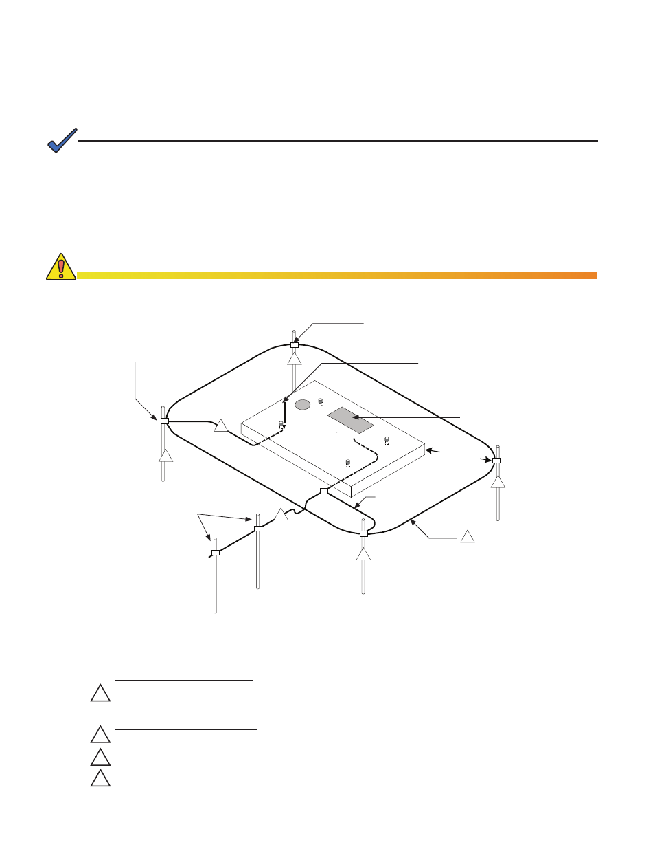
Fig. 2-3, Suggested Grounding Method
• Alpha generally recommends using the grounding method illustrated below. However, the grounding
method appropriate for a particular site depends on local codes, the NEC (National Electric Code), and
other site-specific characteristics.
• Alpha Technologies recommends 5 ohms maximum ground resistance between enclosure and ground
rods, in accordance with IEEE 1100-1999 Powering and Grounding Electronic Equipment.
• Alpha Technologies assumes no responsibility or liability for failure of the installer to comply with the
requirements of all applicable local and national codes. Where allowed, exothermic welding may be used
as an alternative to Burndy clamps and connectors.
NOTE:
Corrosion-proof, twenty-five-year connections suitable for direct burial must be used.
CAUTION!
Service Grounding (required)
#6 bare copper wire from service entrance ground bar, with two 1/2" X 8' (12.7mm x 2.4m) copper
ground rods, driven at least six feet (1.8 meters) apart.
Lightning Protection (optional)
Four 1/2" X 8' (12.7mm x 2.4m) copper ground rods, driven at least two feet from pad.
#6 bare copper wire loop, at least 30" (762mm) below grade, and terminated at each ground rod.
#6 bare copper wire from loop to enclosure ground bar in service entrance.
1
2
3
4
4
1
2
2' min.
2
2
2
Burndy YGHP58C2W-3 or Equivalent
Burndy YGHP58C2W-2TN or Equivalent
Terminate at Service Entrance Ground Bar
Terminate at Enclosure Ground Bar
3
8' (2.4m) Ground Rods
6’ (1.8m) Apart (min.)
#2 AWG
2' (0.6m)
min.