8 installing the xm series 2 power supply, 0 installation – Alpha Technologies Node Power Supply User Manual
Page 35
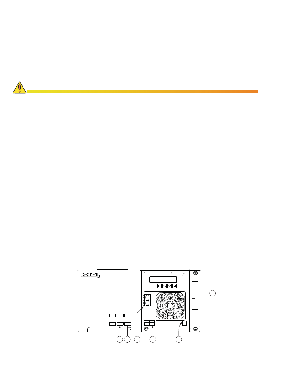
4. After verifying that the batteries, battery connections, and battery cables are connected
properly, plug the battery cable connector from the battery string into the power supply’s
BATTERY INPUT connector (4). The connector is keyed and color-coded to fi t in only one
direction.
5. Plug the Remote Temperature Sensor into the TEMP PROBE connector located on the
Inverter Module assembly on the front of the power supply (5).
6. If applicable, plug the optional Local/Remote Indicator lamp (LRI) cable into the LRI
connector (6).
7. If you are installing a Tamper Switch (TMPR SW), plug it into the 2-pin TMPR connector,
and plug the transponder cable into the transponder TMPR connection (7).
8. Plug the connector from the SPI into the power supply’s OUTPUT 1A (8). If the enclosure
has the optional AC Indicator (ACI) lamp, plug the connector from the SPI into the ACI
and the connector from the lamp into the power supply’s OUTPUT 1A. If the PIM option is
installed, connect a second SPI to OUTPUT 2. Make sure that the SPIs “ALT/ON” switch
is in the ON position.
9. If the installation includes a Module Retaining Cable option, attach the end of the cable to
the hole provided at the top, rear, center of the enclosure. Thread the cable through the
power supply handle and clip it back on itself.
10. The installation is complete. Do Not apply AC power to the power supply or switch
the Inverter Module’s BATTERY BREAKER ON. Refer to the power supply Operator’s
Manual for Start-up and Test procedures.
2.8
Installing the XM Series 2 Power Supply
Installation Procedure:
1. Before installation, inspect the power supply for damage or loose connectors.
2. Place the XM Series 2 Power Supply on the equipment (top) shelf of the enclosure.
3. Switch the BATTERY BREAKER (3) on the front of the power supply OFF. This prevents
the inverter from starting when the batteries are fi rst connected to the power supply.
Check the polarity and voltage of the battery cable connector with a voltmeter before proceeding.
Connecting the battery string or strings to the power supply with incorrect polarity may cause a
short-circuit, and possible equipment damage. Check all battery connections for proper installation.
For complete battery installation procedures, see the “Battery Installation” section in this manual.
CAUTION!
OUTPUT 2
OUTPUT 1A
LRI
Battery
Input
Temp
Probe
Battery
Breaker
OUTPUT 1B
N+1
N+1
6
8
3
4
5
7
Fig. 2-20, XM Series 2 Power Supply
35
031-295-B0-001 Rev.A
2.0 Installation