Engine control module (ecm), 1 2 j6, 4 ecm input voltage and line sense configurations – Alpha Technologies ECM User Manual
Page 38
38
TM
744-862-C0-003 Rev.C
Engine Control Module (ECM)
4.4
ECM input voltage and line sense configurations
The ECM has 120/240VAC input voltage and line sense capabilities, which
must be configured separately. The ECM PCBA part number 704-630-XX must be
configured for 120/208/240VAC line sense via DIP Switch SW5-5 and SW5-6 as
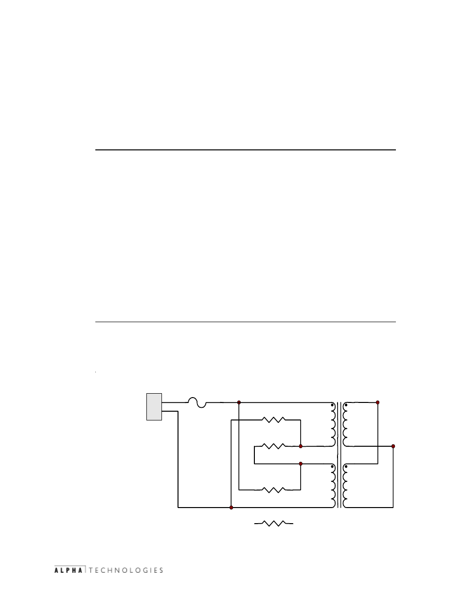
shown in table 4-1. The default setting is 120VAC. The logic transformer (T1)
located on the GRI power board part number 704-634-XX must also be configured
for the correct input voltage by installing zero ohm jumpers R1-R4. Install R1 & R2
for 120VAC operation or R3 & R4 for 240VAC operation as shown in figure 4-4. The
default setting is 120VAC. The following two options are provided for clarification:
Option 1 (Recommended)
Configure ECM power board for an input voltage of 120VAC by installing R1 &
R2 and removing R3 & R4 (default). Configure DIP SW5 on the ECM board for either
120VAC or 240VAC line sense depending on the input voltage configuration of
the XMS2 power supplies being used. In other words, always power the ECM with
120VAC and set DIP SW-5 for the input voltage of the XMS2 power supplies being
used (120VAC or 240VAC). As long as SW-5 is set correctly, the ECM will properly
scale the voltage for status monitoring purposes.
Install the 120VAC power cable (y-adapter) to both the input line sense of the
ECM and the input power to the ignition battery charger (L1 to neutral) as shown
in Figure 4-3. This is the preferred configuration since the battery charger is only
rated for 120VAC operation and the ECM’s default configuration is 120VAC. The
120VAC ignition battery charger is only used on the 2.7/3.0kW APUs.
Note: The ECM will properly sense a line loss on a 240VAC (L1-L2) system even
though it’s only monitoring 120Vac (L1-Neutral) as long as SW-5 is set for 240VAC.
This is based on the fact that the ECM is monitoring the secondary winding of a
centered tapped single-phase transformer from utility power.
Option 2
Configure the power board jumpers R3 and R4 and the DIP SW-5 on the ECM
for 240VAC operation. Install a 240VAC line sense cord for the ECM and a separate
120VAC power cord for the ignition battery charger. When R1 and R2 are installed,
VAC=120. When R3 and R4 are installed, VAC=240.
T1
1
2
J6
120/240VAC
AC LINE
SENSE
F3
120/240V
R1
R2
R3
240V
120V
120V
12V
12V
250mAMP 250V SB
240 V
R4
(p/n 704-634-XX)
Fig. 4-5 ECM Power Board