Engine control module (ecm), 5 standard ecm-transponder interconnection – Alpha Technologies ECM User Manual
Page 31
31
TM
744-862-C0-003 Rev.C
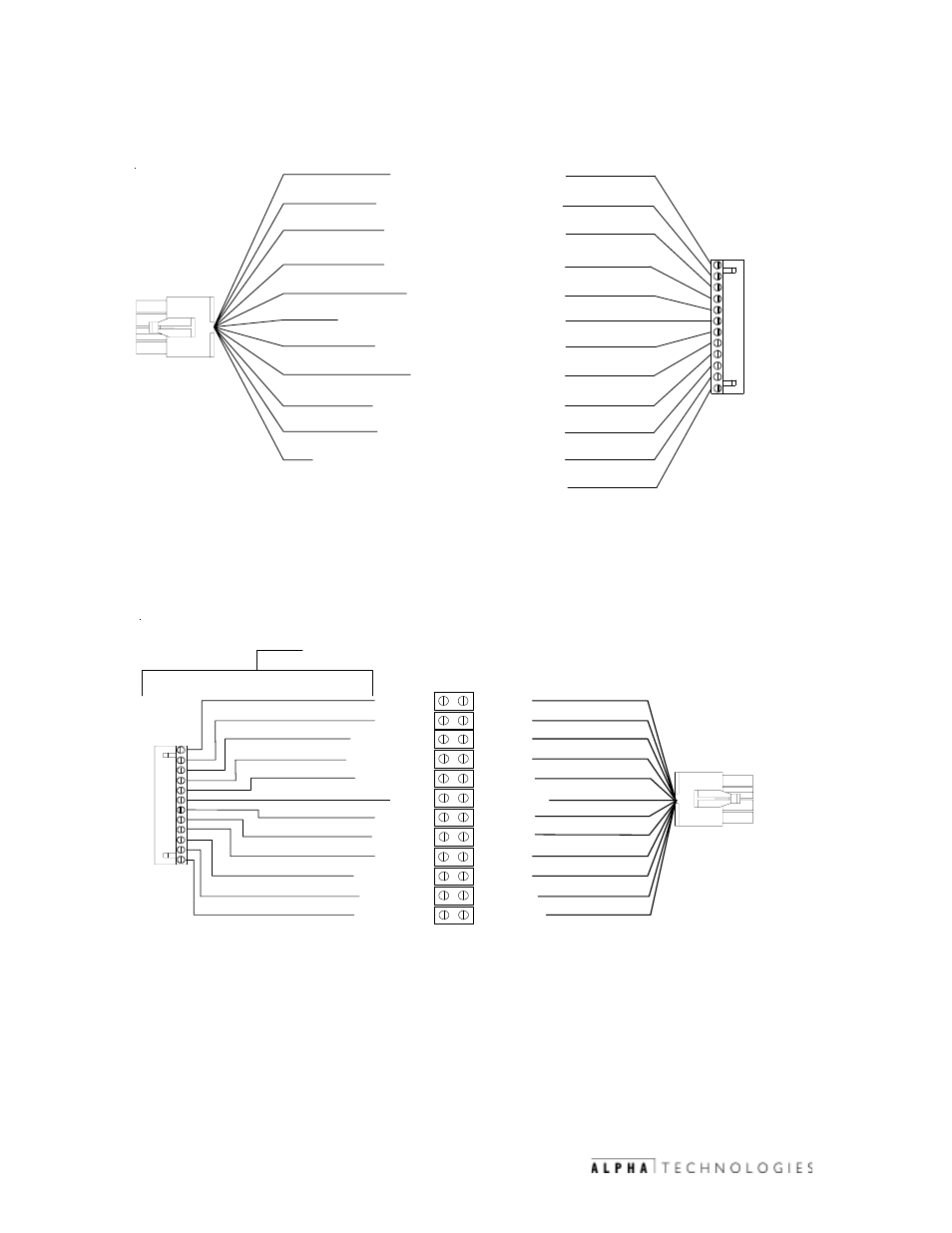
Engine Control Module (ECM)
PIN 4, W4, GAS HAZARD (Brown wire)
PIN 5, W5, TEST FAIL (Blue wire)
PIN 6, W6, ENCLOSURE ALARM (White/Red wire)
PIN 7, W7, ENGINE STATUS (Yellow wire)
PIN 8, W8, TAMPER (White wire)
PIN 3, W3, ENGINE ALARM (Gray wire)
PIN 9, W9, OUTPUT COMMON (Black wire)
PIN 2, W2, MINOR ALARM (Green wire)
PIN 10, W10, ENGINE RUN (Orange wire)
PIN 1, W1, MAJOR ALARM (Red wire)
PIN 11, W11, ENGINE RUN RETURN (White/Black wire)
Not Used
1
2
3
4
5
6
7
8
9
10
11
12
1
2
3
4
5
6
7
8
9
10
11
12
BLU
W
/
WHT
RED
BLACK
BLK
W
/
WHT
GRN
W
/
WHT
GRN
W
/
BLK
BLUE
GREEN
ORANGE
WHITE
WHT
W
/
BLK
RED
W
/
BLK
RED
GREEN
GRAY
BROWN
BLUE
WHITE
/
RED
YELLOW
WHITE
BLACK
ORANGE
WHT
/
BLK
NOT
USED
USER
-
SUPPLIED
15
CONDUCTOR
BELDEN
CABLE
3.5
Standard ECM-Transponder Interconnection
Fig. 3-2 Standard Transponder-to-ECM interconnect cable, collocated applications
Fig. 3-3 Standard Transponder-to-ECM interconnect cable, remote applications
- AlphaCell GelCell Series (32 pages)
- FXM 650, 1100, 2000 UPS (96 pages)
- Cordex 48-1.2kW (68 pages)
- Radium MiniBay (57 pages)
- Fiber Backhaul Enclosure (FBE) (19 pages)
- FBE2322 Enclosure System (38 pages)
- FlexNet PMR, GMR Series (49 pages)
- Te25xh (38 pages)
- FlexNet MPS48-12M - Technical Manual (33 pages)
- FlexNet MPS48-12M - Quick Start Guide (2 pages)
- FlexNet ELPM 300-48D (25 pages)
- FlexNet FMPS (40 pages)
- FlexPoint AX Series (34 pages)
- FlexPoint FPR1207-F - Technical Manual (18 pages)
- FlexPoint FPR1207-F - Quick Start Guide (2 pages)
- AlphaGen PN-6x-T 7.5kW 48VDC - Installation and Operation Manual (79 pages)
- AlphaGen CE-3x2 5K-T 48Vdc (95 pages)
- AlphaGen PN-6x-T 7.5kW 48Vdc (95 pages)
- AlphaGen 3.5_5.0kW Kohler COM5 (80 pages)
- Security Bar Field For UPE-3, UPE-6, UPE-M3, UPE-M6, PN Series and CE Series (2 pages)
- AMPS80 HP (116 pages)
- 255A Bypass Switch (24 pages)
- AMP24 HP (108 pages)
- FXM350_Micro350 UPS (112 pages)
- CFR 600, CFR 600XT, CFR 1000 (70 pages)
- BPS Series Bypass Switch (36 pages)
- CFR Intelligent Interface Device (54 pages)
- CFR Redundant Control Unit (23 pages)
- CFR 5000, CFR 5000RM (88 pages)
- CFR 3000, CFR 3000RM (86 pages)
- CFR 1500, CFR 1500RM (83 pages)
- CFR 1500, CFR 2000, CFR 2500, CFR 3000 (76 pages)
- Continuity: 1000_2000_3000 (48 pages)
- Continuity Battery Pack (20 pages)
- Continuity: 6K_10K (52 pages)
- Micro, Micro XL, Micro XL3 UPS (99 pages)
- Micro Secure UPS (80 pages)
- Te17 (32 pages)
- Te45 (68 pages)
- Te41, 48V (76 pages)
- Te41, 24V (72 pages)
- Te43 (60 pages)
- AlphaGuard AG-CMT Installation (2 pages)
- AlphaGuard AG-CMT-3SC_4SC-P (2 pages)
- Digital Midtron DM-3200 AT (2 pages)