Engine control module (ecm), 3 system interface, continued, Chestec corporation – Alpha Technologies ECM User Manual
Page 37: Port washington, ny, Model hic, Pwr-gri
37
TM
744-862-C0-003 Rev.C
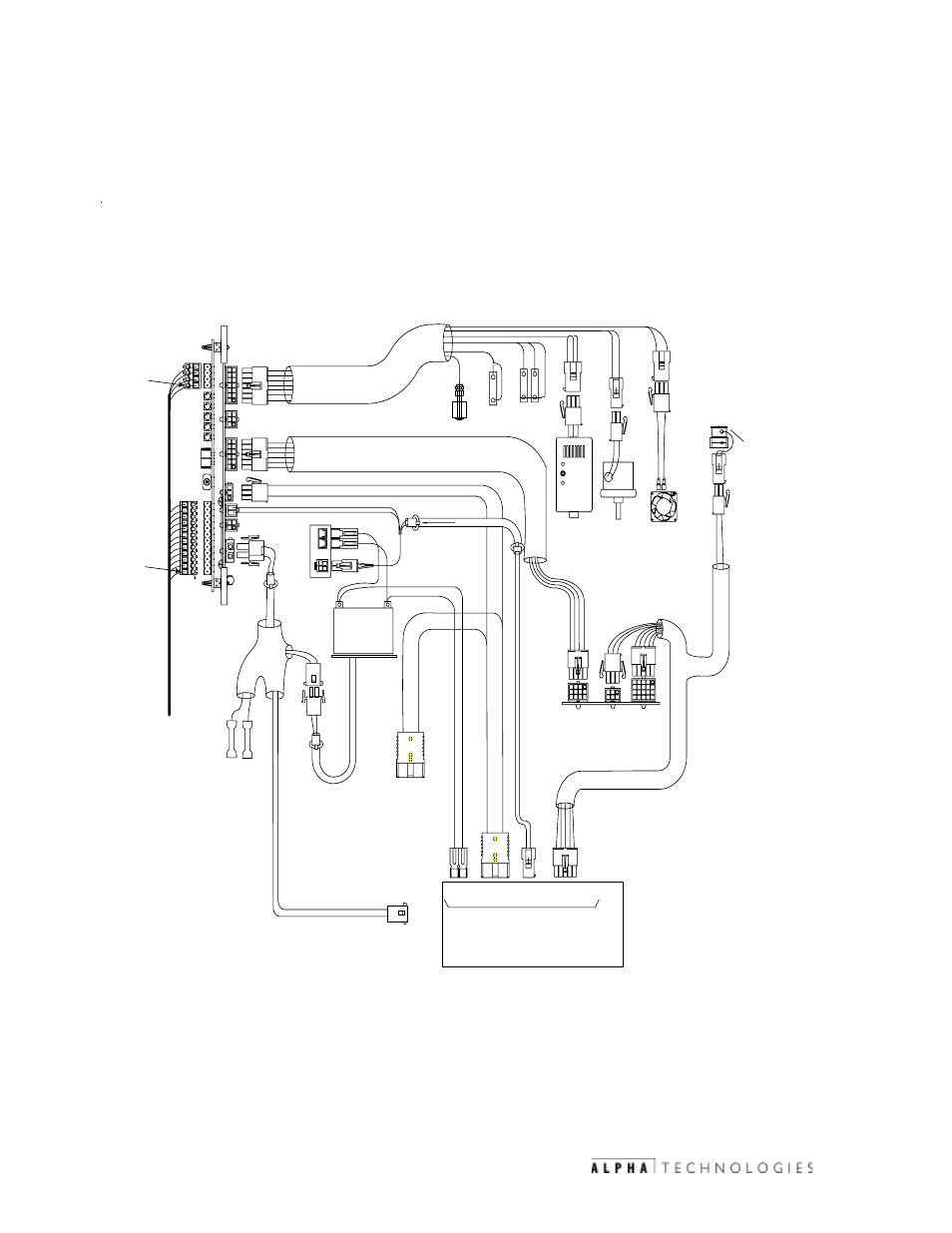
Engine Control Module (ECM)
The illustration below shows the interconnection between the ECM,
engine-generator controller, and enclosure safety sensors.
4.3
System Interface, continued
POS
DC
OUT
ENGINE ALTERNATOR
COMPARTMENT
1
2
PWR-GRI
APU CONTROL
PAD
WATER
DOOR
SHEAR
ALARM
NE
G
LINE
SENSE
INTERFACE
INTERFACE
GAS
SENSOR
INTRUSION
OPEN
INV BATTERY
SENSE
NE
U
T
1
20V
J10
J6
GHD
PLUG
ALARM
INTERFACE
Chestec Corporation
842
Port Washington, NY
ALAR
M
MODEL HIC
GAS
DETECTOR
RESET
READ
Y
FUEL
LOW
PRESSURE
LFP
PLUG
FAN
IGNITION
BATTERY
+
-
OUTPUT
PO
S
NE
G
D
CN-
DC
P
APU
CONTROL
PCB
POS
NE
G
IG
N
BAT
T
LINE
SENSE
1
2
3
4
J
2
BL
K
R
E
D
DC
POWER
RED
BATTERY
HEATER
OPTION
- 120
V
DC
OUTPUT
BUS
CHARGER
CONTROL
ECM
-
+
SOLENOID
GAS
GSC
PLUG
J4
J8
BLOCK HEATER
OPTION
-
+
12 pin
AMP
6 pin
ML
20 pin
AMP
15 pin
MML
2 pin
MML
See Alpha 5 Manual,
Kohler Power Systems document
# TP-6076, 12/99
PIN 1
PIN 1
Fig. 4-4 ECM/APU Interconnection, 5.0 kW configuration
- AlphaCell GelCell Series (32 pages)
- FXM 650, 1100, 2000 UPS (96 pages)
- Cordex 48-1.2kW (68 pages)
- Radium MiniBay (57 pages)
- Fiber Backhaul Enclosure (FBE) (19 pages)
- FBE2322 Enclosure System (38 pages)
- FlexNet PMR, GMR Series (49 pages)
- Te25xh (38 pages)
- FlexNet MPS48-12M - Technical Manual (33 pages)
- FlexNet MPS48-12M - Quick Start Guide (2 pages)
- FlexNet ELPM 300-48D (25 pages)
- FlexNet FMPS (40 pages)
- FlexPoint AX Series (34 pages)
- FlexPoint FPR1207-F - Technical Manual (18 pages)
- FlexPoint FPR1207-F - Quick Start Guide (2 pages)
- AlphaGen PN-6x-T 7.5kW 48VDC - Installation and Operation Manual (79 pages)
- AlphaGen CE-3x2 5K-T 48Vdc (95 pages)
- AlphaGen PN-6x-T 7.5kW 48Vdc (95 pages)
- AlphaGen 3.5_5.0kW Kohler COM5 (80 pages)
- Security Bar Field For UPE-3, UPE-6, UPE-M3, UPE-M6, PN Series and CE Series (2 pages)
- AMPS80 HP (116 pages)
- 255A Bypass Switch (24 pages)
- AMP24 HP (108 pages)
- FXM350_Micro350 UPS (112 pages)
- CFR 600, CFR 600XT, CFR 1000 (70 pages)
- BPS Series Bypass Switch (36 pages)
- CFR Intelligent Interface Device (54 pages)
- CFR Redundant Control Unit (23 pages)
- CFR 5000, CFR 5000RM (88 pages)
- CFR 3000, CFR 3000RM (86 pages)
- CFR 1500, CFR 1500RM (83 pages)
- CFR 1500, CFR 2000, CFR 2500, CFR 3000 (76 pages)
- Continuity: 1000_2000_3000 (48 pages)
- Continuity Battery Pack (20 pages)
- Continuity: 6K_10K (52 pages)
- Micro, Micro XL, Micro XL3 UPS (99 pages)
- Micro Secure UPS (80 pages)
- Te17 (32 pages)
- Te45 (68 pages)
- Te41, 48V (76 pages)
- Te41, 24V (72 pages)
- Te43 (60 pages)
- AlphaGuard AG-CMT Installation (2 pages)
- AlphaGuard AG-CMT-3SC_4SC-P (2 pages)
- Digital Midtron DM-3200 AT (2 pages)