Engine control module (ecm), 2 ecm configuration – Alpha Technologies ECM User Manual
Page 35
35
TM
744-862-C0-003 Rev.C
Engine Control Module (ECM)
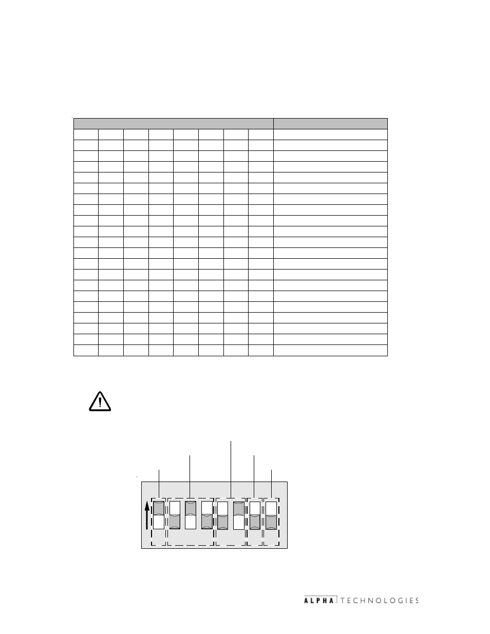
Output voltage configuration
Input voltage configuration
ON
1 2 3 4 5 6 7 8
Interface
Enable Autotest
4.2
ECM Configuration
The ECM configuration is required for interface type, output voltage,
input voltage and reserved functions. The following should be used to
configure the ECM:
(Switch settings shown below are for a CE-3X2 with 120 VAC input and 36VDC output.)
*NOTE:
Programming parameters that affect the Autotest
feature via Status Monitoring will override this switch
setting.
Engine Start/Run Signal
(Alpha p/n 704-630-xx-xxx)
E C M S w i tc h 5 S e t t in g s
M e a n i n g
1
2
3
4
5
6
7
8
1 = O N , 0 = O F F
0
N o n s ta n d a r d G R I in te r fa c e
( 7 .5 k W S e r ie s )
1
S ta n d a r d G R I in te r fa c e , C E - 3 X 2
0
0
0
In v a lid o u tp u t v o lta g e c o n fig u ra tio n
0
0
1
2 4 V D C O u tp u t
0
1
0
3 6 V D C O u tp u t
0
1
1
4 8 V D C O u tp u t
1
0
0
9 6 V D C O u tp u t
1
0
1
1 2 0 V D C O u tp u t
1
1
0
2 0 8 V D C O u tp u t
1
1
1
2 4 0 V D C O u tp u t
0
0
In v a lid in p u t v o lta g e c o n fig u r a tio n
1
0
1 2 0 A C in p u t
0
1
2 0 8 3 -p h a s e in p u t
1
1
2 4 0 V A C in p u t
0
0
N o a ffe c t
1
0
N o a ffe c t
1
0
E C M D r iv e s s ta r te r w ith th e " E n g in e S ta r t"
S ig n a l.
1
1
" E n g in e S ta r t" S ig n a l b e c o m e s
" E n g in e R u n " a n d is h e ld lo w b y E C M
0
A u to te s t tu r n e d O F F .*
1
A u to te s t s e q u e n c e e n a b le d w ith 1 4 - d a y te s t
in te r v a l
Fig. 4-2 SW5, ECM PCBA
Table 4-1 ECM switch configurations.