Alarm and signal wiring connections for cxcm, Analog inputs for cxcm, 15 alarm (relay) outputs for cxcm – Alpha Technologies Cordex 48-1kW 23 4000W User Manual
Page 17: 1 lvd control, 2 system fail output
A
RGUS
T
ECHNOLOGIES
C
ORDEX
48-1
K
W 23" S
HELF FOR
S
YSTEMS UP TO
4000W
WITH
D
ISTRIBUTION
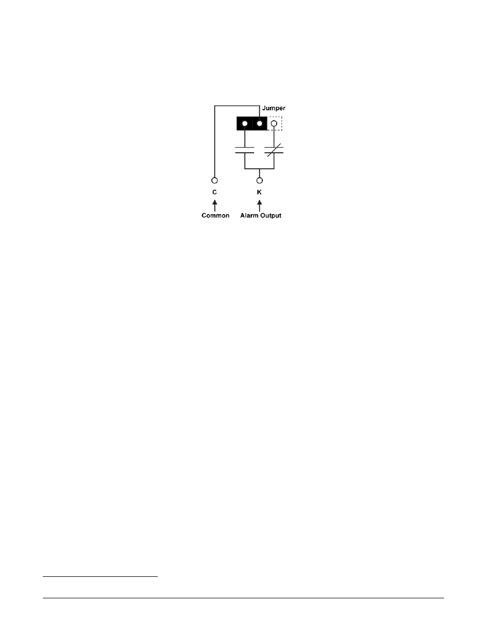
4.15 Alarm (Relay) Outputs for CXCM
Terminals provide contacts for extending various alarm or control signals. Each relay output can be wired (jumper
selectable) for NO or NC operation during an alarm or control condition. See Figure 5.
Figure 5–Showing relay connections
Relays can be programmed to energize or de-energize during an alarm condition (see CXC Software manual).
When the CXC reset button is pressed or power is lost, all relays de-energize.
These relays could be used for additional external LVD contactor control; however, this would not provide the
redundant LVD control as with the assigned output pins described below.
4.15.1 LVD Control
The LVD Control functions can be hardwired directly from the assigned output pins (+ and -) to an external LVD
contactor (or panel). See Controls Menu Defaults in the CXC Software manual. Note: this connection is factory-
equipped for List 86 and List 87.
4.15.1.1 Redundant LVD Control Circuit
The shelf backplane
1
provides circuitry to override the LVD Control function. This is a safety
measure to protect against accidental load disconnect should the CXCM be removed from the
shelf. This protection is also necessary during CXCM reset.
The OUT voltage is 46V and the IN voltage is 51V. Ensure the CXCM LVD voltages are set
outside of this range. Note: controller Relay 1 must be set to ENERGIZED for the LVD to
operate properly.
4.15.2 System Fail Output
Terminals provide connections for a system (controller) fail relay. This fail-safe relay (i.e. it is de-energized
during an alarm condition) can be wired for NO or NC operation.
1
Argus #707-340-20 for the CXCM. See Customer Connections drawing at the rear of this manual.
030-704-C0
R
EV
A
P
AGE
11
OF
14