Ethernet side access (list option 93), 11 cxcm battery –48v connection, 12 alarm and signal wiring connections for cxcm – Alpha Technologies Cordex 48-1kW 23 4000W User Manual
Page 14: 1 ethernet port for network connection, 2 ethernet port for local connection, 3 rs-232 serial (craft) port for local connection
A
RGUS
T
ECHNOLOGIES
C
ORDEX
48-1
K
W 23" S
HELF FOR
S
YSTEMS UP TO
4000W
WITH
D
ISTRIBUTION
4.10.1 Ethernet Port for Network Connection
The Ethernet port is designed for CXCM connection to a user supplied network via an RJ-45 jack. Connect to the
Cordex shelf using a standard network cable. Pinouts are shown in drawing 030-704-08.
4.10.2 Ethernet Port for Local Connection
Local access is also possible through the Ethernet port connection using a standard crossover cable.
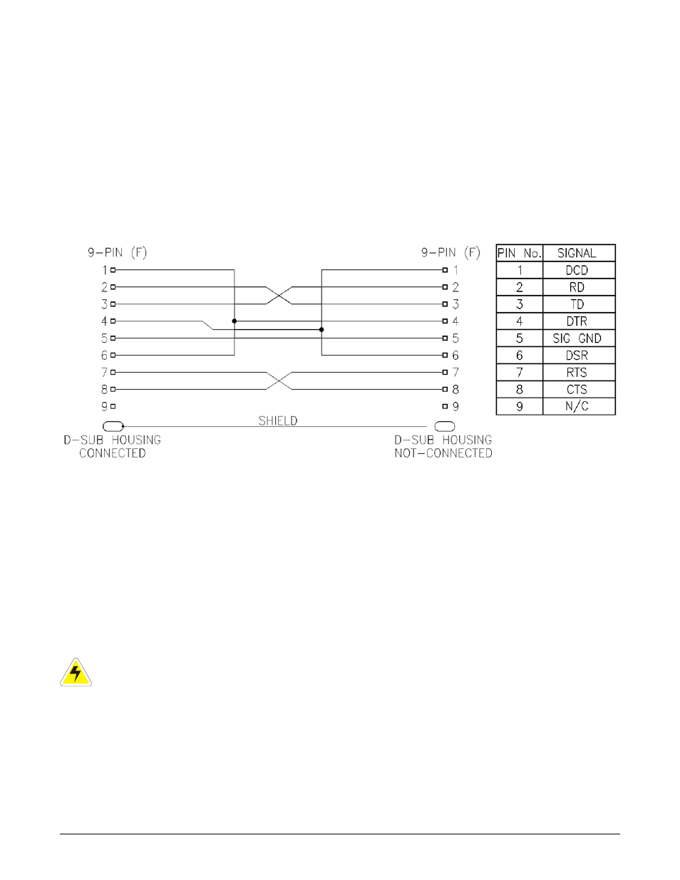
4.10.3 RS-232 Serial (Craft) Port for Local Connection
Local access to the CXC is possible through the front panel RS-232 serial port using a null modem cable. See
Figure 3 below. The communication protocol supports a web interface. The remote screen display is an enhanced
version of the CXC’s front panel display.
Figure 3–NULL modem pinouts
4.11 CXCM Battery –48V Connection
The Battery -48V should be connected at the battery system voltage terminal for CXCM reference when a battery
disconnect device is used. It is critical to CXCM operation as it ensures a source of power to the CXCM should
the disconnect device open the circuit. A 1/4” spade (quick connect) connector is provided on the CXCM portion
of the shelf backplane. #18 AWG wire is recommended. Note: this connection is factory-equipped for List 87.
4.12 Alarm and Signal Wiring Connections for CXCM
For terminal block connections, the recommended wire sizes are 0.823 to 0.129mm
2
(#18 to #26 AWG) for the
temperature range of 0 to 50 deg. C (as per UL/CSA).
For insulation displacement receptacles, the recommended wire size is 0.823mm
2
(#18 AWG).
CAUTION: to reduce risk of fire, use only 0.129mm
2
(#26 AWG) or larger wire.
P
AGE
8
OF
14
030-704-C0
R
EV
A