Cxcm battery –48v connection, 13 analog inputs for cxcm, 1 voltage – Alpha Technologies Cordex 48-1kW 23 4000W User Manual
Page 15: 2 current, Caution: to reduce risk of fire, use only 0.129mm
A
RGUS
T
ECHNOLOGIES
C
ORDEX
48-1
K
W 23" S
HELF FOR
S
YSTEMS UP TO
4000W
WITH
D
ISTRIBUTION
CAUTION: to reduce risk of fire, use only 0.129mm
2
(#26 AWG) or larger wire.
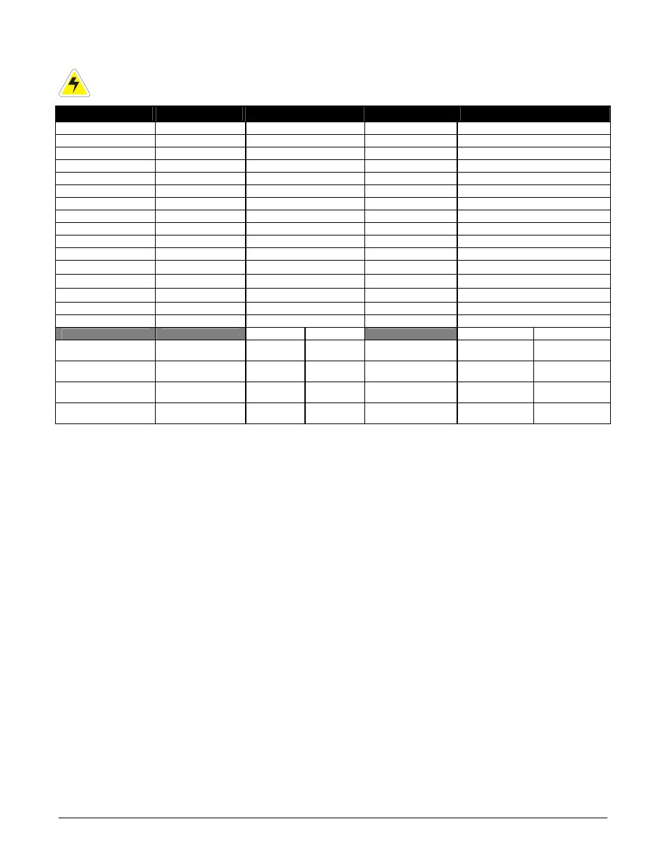
Description
Default Name
Signal Type
Range
21-22(common)*
Alarm Output 2
LVD2
NC/COM/NO (JP2)
60VDC / 1A
19-20(common)*
Alarm Output 3
LVD3
NC/COM/NO (JP3)
60VDC / 1A
17-18(common)*
Alarm Output 4
System Minor
NC/COM/NO (JP4)
60VDC / 1A
15-16(common)*
Alarm Output 5
System Major
NC/COM/NO (JP5)
60VDC / 1A
13-14(common)*
Alarm Output 6
AC Mains Hi-Low
NC/COM/NO (JP6)
60VDC / 1A
11-12(common)*
Alarm Output 7
Not assigned
NC/COM/NO (JP7)
60VDC / 1A
9-10(common)*
Alarm Output 8
Not assigned
NC/COM/NO (JP8)
60VDC / 1A
23-25**
Alarm Output 0
System Fail Output
NO/COM/NC
60VDC / 1A
E1
Battery -48V
Battery -48V
Neg (-)
20—60VDC
J3
Ethernet Port
Ethernet Port
N/A
N/A
P1
LVD Control
LVD Control
Polarized
0—60V / 1A
P5, 1-2***
Digital Input 1
Distribution Fuse (Alarm)
Pos (+) or Neg (-)
0—60VDC
P5-3, P6-1***
Digital Input 2
Distribution CB (Alarm)
Pos (+) or Neg (-)
0—60VDC
P6, 2-3***
Digital Input 3
Battery CB (Alarm)
Pos (+) or Neg (-)
0—60VDC
P7
Voltage Input 1
Discharge Voltage
Pos (+) or Neg (-)
0—100VDC
P8
Current Input 1
Discharge Current
Pos (+) or Neg (-)
±50mV
L120 L124
L120 L124
1-2****
General Input 1
Temp
Probe #1
Voltage
#3
Pos (+) or Neg (-)
0-20VDC
0-60VDC
3-4****
General Input 2
Temp
Probe #2
Voltage
#4
Pos (+) or Neg (-)
0-20VDC
0-60VDC
5-6****
General Input 3
Not
Used
Voltage
#5
Pos (+) or Neg (-)
Not Used
0-60VDC
7-8****
General Input 4
Bipolar
Voltage
Temp
Probe #1
Pos (+) or Neg (-)
±60VDC
0-20VDC
Table B–Wiring connections for CXCM
*
Jumper selectable NO or NC Form C contacts. Can be configured to de-energize on alarm (DOA) of energize on alarm (EOA).
**
System Fail output relay is fail-safe and will de-energize during an alarm condition.
***
See Table D for definitions of logic and system.
****
Bipolar (Voltage Input) is ±60VDC, Voltage (Input) is 0—60VDC, Temp Probe is 0—20VDC with power source.
To aid the user with installation, frequent reference is made to drawings located at the rear of this manual. Custom
configurations may be detailed within the Argus power system documentation package.
4.13 Analog Inputs for CXCM
CAUTION: Ensure the correct polarity is used for all input cable terminations.
The analog input channels are used to monitor various types of electrical signals. Some of the analog channels are
reserved for specific signals, while others are designated as general-purpose inputs, which accommodate various
types of analog signals. The input cables should be bundled together and routed through the entry holes of the
shelf, if applicable.
4.13.1 Voltage
Voltage Input #1 (discharge voltage per CXC software) terminals on the shelf provide connections to an optional
secondary voltage input. For example, this can be terminated to the load side of an LVD contactor to monitor load
voltage.
Voltage Input #2 (charge voltage per CXC software) is wired internally to the rectifier output voltage of the shelf.
This is used as the reference for system alarming (such as high voltage) and control (such as low voltage
disconnect).
4.13.2 Current
Current Input #1 terminals provide connections (factory-installed) to the system current shunt normally used to
monitor discharge (load) current.
030-704-C0
R
EV
A
P
AGE
9
OF
14