14 digital inputs for cxcm, 3 general-purpose, 1 connection method – Alpha Technologies Cordex 48-1kW 23 4000W User Manual
Page 16: 2 programming the digital input
A
RGUS
T
ECHNOLOGIES
C
ORDEX
48-1
K
W 23" S
HELF FOR
S
YSTEMS UP TO
4000W
WITH
D
ISTRIBUTION
4.13.3 General-Purpose
Terminals provide connection pairs for various analog inputs such as temperature sensors. These are configured at
the time of ordering. The configuration determines whether the signals allowed are to be bipolar (may vary in
either polarity from zero; e.g., +/-60VDC) or unipolar (may vary positive from zero; e.g., 0 to +60VDC). The
CXC software is pre-configured to monitor converter voltage through input channel GP1.
4.13.3.1 Temperature Sensor
Terminals, of the general purpose grouping, may be configured as temperature input channels and
provide connections for up to two temperature sensors. A voltage is supplied to these terminals
for sensor measurements.
4.14 Digital Inputs for CXCM
The digital input channels (factory-installed) are used to monitor various alarm and control signals. All input
channels are voltage activated and accept a bipolar (i.e. negative or positive) DC signal directly. The CXCM is
programmed for the specific functions listed in Table B.
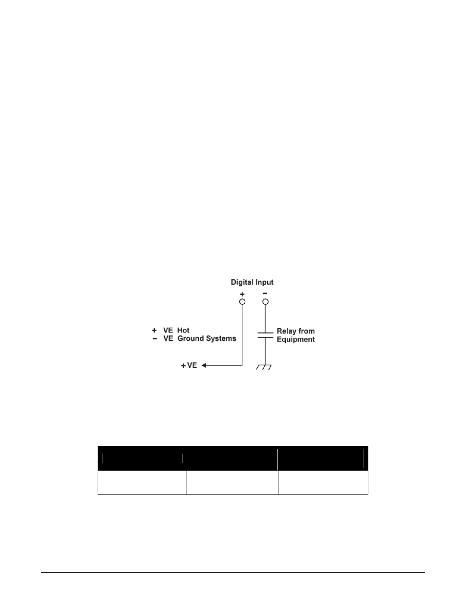
4.14.1 Connection Method
Typical Argus systems use the “reset with Hot and trigger with Ground” connection. The digital input is wired in
such a way that the Hot is wired directly into one of the input terminals; e.g., positive input for +24V or negative
for –48V systems. The other input terminal is wired to the Ground (common) of the system through a relay (dry
contact – usually located on the equipment requiring monitoring). This method (see Figure 4) allows the digital
input to receive (or not receive) a Ground signal on an alarm.
Figure 4–Showing digital input connection method
4.14.2 Programming the Digital Input
The digital input channels can be programmed for “active high” or “active low.” Active high indicates “alarm on
the presence of a ground signal” and active low indicates “alarm on the removal of a ground signal.” See CXC
Software manual for detailed instruction on programming.
Voltage Range (VDC)
Voltage Level (VDC)
Considered As “0” (Off)
Voltage Level (VDC)
Considered As “1” (On)
0—60
(system voltage setting)
0—3 18—60
Table C–Voltage level definitions for digital inputs
P
AGE
10
OF
14
030-704-C0
R
EV
A