Cmdl, Latching deluge pilot, Installation / operation / maintenance – Cla-Val 834-05 User Manual
Page 17: Model
INTRODUCTION
The Cla-Val Model Latching Deluge Pilot is a three (3) way, two
(2) position, pneumatic or hydraulically operated, Normally
Closed, pilot valve. Manual Reset Deluge Pilots will not be reset
or positioned by application of pilot supply pressure alone. The
pilot must be manually held(knob pulled out), while pilot supply is
present to establish the "set position". These valves can employ
relatively low pressure applied at the Pilot Supply (PS) port to
enable higher pressure to be relayed through the Inlet (IN) and
Outlet (OUT) ports. It is designed to block the inlet supply pres-
sure and exhaust accumulated outlet pressure whenever the pilot
supply pressure falls to 20 psi or if the stem is pushed inward.
Connections on the Latching Deluge Pilot and their functions are
shown as follows:
Connection - Function
Inlet (IN) -Supply Inlet (Pressure Applied 20-250 PSI)
Outlet (OUT) - To pressurize deluge valve control port.
Exhaust (EXH) – To bleed pressure from Deluge valve control port.
(Outlet to Exhaust).
Pilot Supply (PS) - Application of pressure (30-250 PSI) for normal
in-service operation (Deluge valve "set-up").
Minimum pilot supply pressure is 30 psi.
Pilot trips at 20 psi.
SHELF (UNACTUATED) POSITION
Supply pressure can not enter the flow control section of the valve
body since the assembly is configured for Normally Closed serv-
ice. Pilot supply pressure at the (PS) port is also prevented from
direct entry into the piston chamber. Additionally, an internal bore
within the stem is aligned with an exhaust vent hole to insure its
complete depressurization. A flow path exists between the Outlet
(OUT) and Exhaust (EXH) ports.
INSTALLATION / OPERATION / MAINTENANCE
O-Ring seals engage the valve wall providing the necessary
pressure isolation. The large internal spring is fully decom-
pressed to maintain the position shown. A shelf position is also
denoted by the stems placement in its inner most location.
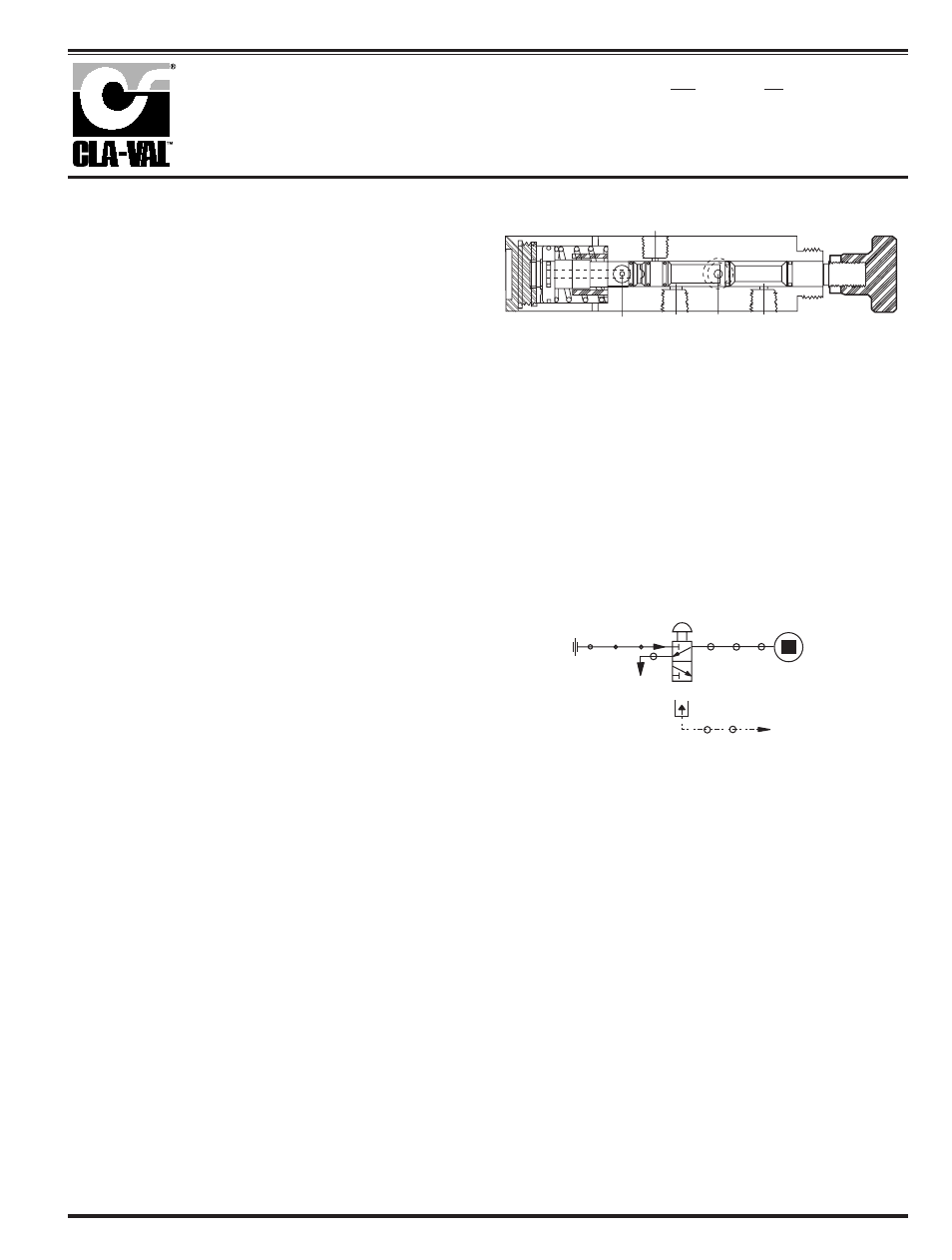
The schematic following, further illustrates the flow paths estab-
lished for the unactuated or a shelf position.
As shown, an internal flow path exists between the Outlet (OUT)
and Exhaust (EXH) ports. The control circuit downstream of the
Outlet (OUT) port is fully depressurized.
Latching Deluge Pilot
OUT
IN
EXH
PS
V
IN
EXH
PULL-TO- RESET
OUT
DELUGE VALVE
CONTROL CHAMBER
STATUS
DELUGE VALVE OPEN
PS
CONTROL
PRESSURE
SOURCE
PILOT STATUS: UNACTUATED
PILOT SUPPLY IS ABSENT OR HAS DECREASED
BELOW "LATCH" HOLDING PRESSURE
KNOB POSITION: IN
PILOT SUPPLY
PRSSURE ABSENT
CMDL
MODEL