130vc-3 – Cla-Val 390-07/3690-07 User Manual
Page 20
130VC-3 Electronic Actuator for 33 Series Pilot Controls
130VC-3
MODEL
INSTALLATION / OPERATION / MAINTENANCE
130VC-3 Electronic Actuator for 33 Series Pilot
Controls
Thank you for purchasing a 33 Series Electronic Control with
130VC-3 “e-Drive” Actuator. With proper maintenance, the actua-
tor will perform indefinitely and provide very accurate and reliable
valve control. It is built with the latest technology utilizing the high-
est quality components.
33 Series Controls
The 33 Series Actuated Pilot Controls for 300 Series Valves
consist of a hydraulic pilot subassembly and 130VC-3 Actuator.
The Cla-Val Model CDHS-33, CRA-33, CRD-33, and CRL-33 pilot
controls are factory set to full adjustment range of the pilot sub-
assembly. The 130VC-3 Actuator accepts a 4 - 20 mA remote
command set point or dry contact closure and positions spring-
loaded hydraulic pilot subassembly as it maintains set point of
pressure or flow rate. The pilot subassembly is automatically linear
between the limit settings.
32 Series Control Operation
A.) The 130VC-3 actuator allows 33 Series Controls to be
used in valve remote control applications where a simple change
of pilot set-point is needed. SCADA instrumentation provides set-
point control and verification communication based on this scale.
The actuator can also be controlled by simple contact closure.
B.) Other suitable valve remote control applications are
where 4 - 20 mA command input signal is calibrated to specific high
and low range values. SCADA instrumentation provides set-point
control and verification communication based on system dynamic
conditions and valve’s re-ranged scale. Using a laptop computer,
the 130VC-3 actuator is calibrated in the field to specific minimum
and maximum pressure or flow control settings that are in direct
proportion to 4 - 20 mA command signal. Once values are estab-
lished, the valve will be linear between limits and set-point will not
exceed limits throughout the 4 - 20 mA signal range. For example,
when actuator is calibrated to 4 mA = 50 psi to 20 mA = 100 psi, a
12 mA command signal will result in a 75 psi set point.
33 Series Actuator Hardware Set-up
BEFORE running actuator or software program, complete the
following hookup steps:
Use good field wiring practices for low voltage DC analog instrumen-
tation wiring (use 20-gauge twisted pair shielded wire minimum).
Avoid potential ground loops. Avoid over tightening wiring connec-
tor fasteners.
The enclosure is rated IP-68 (similar to NEMA 6P) submersible for
short periods of time. It is not intended for continuous underwater
use. Consult Cla-Val factory technical support if you have questions.
The ten-wire ten meter cable is permanently attached to 130VC-3
actuator and should be terminated in suitable junction box or
directly into an above grade RTU or similar device. Care should be
used when attaching to wires to avoid damage. Installation of suit-
able protection from lightning is highly recommended.
There are no user serviceable parts inside the actuator and tam-
pering or opening it will void the warranty. The ten-wire actuator
cable is permanently attached. Internal damage not covered by
warranty will occur if cable is removed.
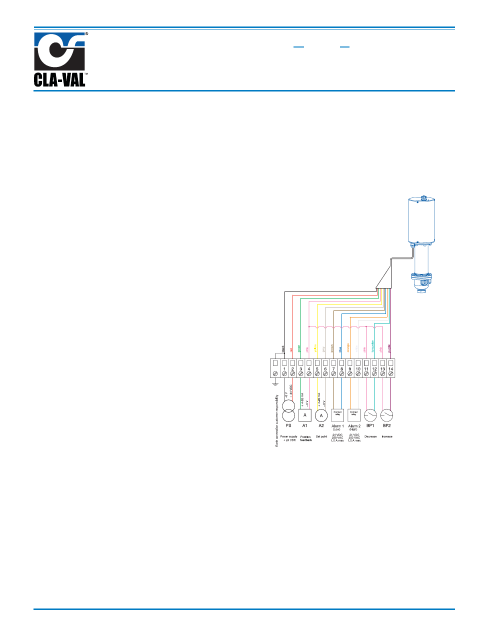
FIELD WIRING STEPS:
Terminate wires only applicable to your application. For example,
minimal wiring requirements for power and remote set point are:
1.) Attach 12 to 24 VDC power to 130VC-3 Actuator cable.
Black wire is for (-) negative; Red wire is for (+) positive. Provide
minimum 500 mA supply.
2.) Attach 4 to 20 mA analog Remote Command Input (from
SCADA system or loop calibrator) to 130VC-3 Actuator cable.
Yellow is positive and Grey is negative.
Download Wiring Diagram from website (www.cla-val.com)
3.) After wiring is complete and actuator is powered, it can be
used with 4 - 20 mA remote command input signal scaled to facto-
ry default pilot control adjustment range (Operation A, above).
Troubleshooting Actuator Set-up
1.) The actuator LED will remain red for approximately 30
seconds after power on, and then will switch to green indicating
actuator is OK and that internal start-up test is complete.
2.) he actuator LED blinks red if there is a problem. After
resolving the problem, reset the actuator by turning power off for
ten seconds then on again.
3.) he actuator blinks red and green if still in the calibration
mode. It will be necessary to finish calibration.
Terminal strip not
supplied for
Illustration
purpose only
*
DO NOT WIRE 24 VDC POWER
*